


7-22
Catalyst 2950 and Catalyst 2955 Switch Software Configuration Guide
78-11380-10
Chapter 7 Clustering Switches
Creating a Switch Cluster
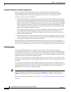
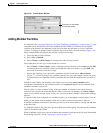
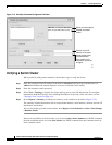
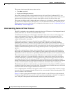
Figure 7-12 Standby Command Configuration Window
Verifying a Switch Cluster
When you finish adding cluster members, follow these steps to verify the cluster:
Step 1 Enter the command switch IP address in the browser Location field (Netscape Communicator) or
Address field (Microsoft Internet Explorer) to access all switches in the cluster.
Step 2 Enter the command-switch password.
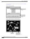
Step 3 Select View > Topology to display the cluster topology and to view link information. For complete
information about the Topology view, including descriptions of the icons, links, and colors, see the
“Topology View” section on page 4-14.
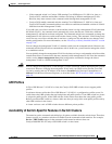
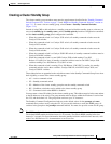
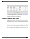
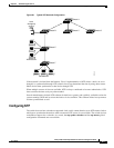
Step 4 Select Reports > Inventory to display an inventory of the switches in the cluster (Figure 7-13).
The summary includes information such as switch model numbers, serial numbers, software versions, IP
information, and location.
You can also display port and switch statistics from Reports > Port Statistics and Port > Port Settings
> Runtime Status.
Instead of using CMS to verify the cluster, you can use the show cluster members user EXEC command
from the command switch or use the show cluster user EXEC command from the command switch or
from a member switch.
3550C (cisco WS-C3550-C-24, HC, ...
NMS-3550-12T-149 (cisco WS-C3550-1
3550-150 (cisco WS-C3550-12T, SC, ...
Active command switch.
Standby command
switch.
Must be a valid IP
address in the same
subnet as the active
command switch.
Once entered, this
information cannot be
changed.
65726