


27-3
Catalyst 2950 and Catalyst 2955 Switch Software Configuration Guide
78-11380-10
Chapter 27 Configuring System Message Logging
Configuring System Message Logging
This example shows a partial switch system message:
00:00:46: %LINK-3-UPDOWN: Interface Port-channel1, changed state to up
00:00:47: %LINK-3-UPDOWN: Interface GigabitEthernet0/1, changed state to up
00:00:47: %LINK-3-UPDOWN: Interface GigabitEthernet0/2, changed state to up
00:00:48: %LINEPROTO-5-UPDOWN: Line protocol on Interface Vlan1, changed state to down
00:00:48: %LINEPROTO-5-UPDOWN: Line protocol on Interface GigabitEthernet0/1, changed
state to down 2
*Mar 1 18:46:11: %SYS-5-CONFIG_I: Configured from console by vty2 (10.34.195.36)
18:47:02: %SYS-5-CONFIG_I: Configured from console by vty2 (10.34.195.36)
*Mar 1 18:48:50.483 UTC: %SYS-5-CONFIG_I: Configured from console by vty2 (10.34.195.36)
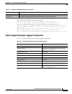
Default System Message Logging Configuration
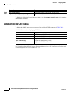
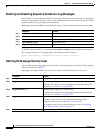
Table 27-2 shows the default system message logging configuration.
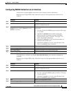
MNEMONIC Text string that uniquely describes the message.
description Text string containing detailed information about the event being reported.
Table 27-1 System Log Message Elements (continued)
Element Description
Table 27-2 Default System Message Logging Configuration
Feature Default Setting
System message logging to the console Enabled.
Console severity Debugging (and numerically lower levels; see
Table 27-3 on page 27-9).
Logging buffer size 4096 bytes.
Logging history size 1 message.
Timestamps Disabled.
Synchronous logging Disabled.
Logging server Disabled.
Syslog server IP address None configured.
Server facility Local7 (see Table 27-4 on page 27-12).
Server severity Informational (and numerically lower levels; see
Table 27-3 on page 27-9).