


1-2
Cisco Catalyst Blade Switch 3040 for FSC Hardware Installation Guide
OL-10694-01
Chapter 1 Product Overview
Front Panel Description
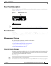
Front Panel Description
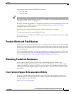
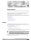
Ten of the ports on the 16-port Gigabit Ethernet blade switch are internal 1000BASE-X ports that
connect to the BX600 system through the backplane. Figure 1-1 shows the console port, the two external
10/100/1000BASE-T copper ports, and the four external SFP module uplink ports that support
1000BASE-SX and 10/100/1000BASE-T copper. Only Cisco SFP modules are supported.
Figure 1-1 The Cisco Catalyst Blade Switch 3040 for FSC
Each port has an associated LED. The BX600 system blade management board controls the System
Status/ID LED.
Blade Switch Console Port
You can connect the switch module through its console port to a PC by using the RJ-45-to-DB9 female
cable that ships with the product. If you need a spare cable, you can order a kit (part number
ACS-DSBUASYN=) directly from Cisco. If you want to attach the switch module to any other device,
such as a terminal server, you might need a different cable. For console port and adapter pinout
information, see the “Connector and Cable Specifications” section on page B-1.
For information on the BX600 system management blade console port, see the BX600 system
documentation.
1 Blade switch 6 Gigabit Ethernet port LEDs
2 Console port 7 SFP module ports
3 Console port LED 8 SFP module port LEDs
4 System Status/ID LED 9 Release latch
5 External Gigabit Ethernet ports
190180
11x
12x
13x
14x
15x
16x
C
o
n
sole
11x
12x
13x
14x
15x
16x
C
O
N
ID
2
3
5
9
4
8
7
6
1