


B-4
Cisco Catalyst Blade Switch 3040 for FSC Hardware Installation Guide
OL-10694-01
Appendix B Connector and Cable Specifications
Cable and Adapter Specifications
Four Twisted-Pair Cable Pinouts for 1000BASE-T Ports
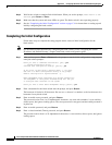
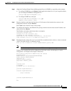
Figure B-5 and Figure B-6 show the schematics of four twisted-pair cables for 10/100/1000 ports on
the blade switch.
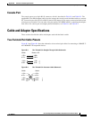
Figure B-5 Four Twisted-Pair Straight-Through Cable Schematic for 10/100/1000 Ports
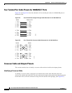
Figure B-6 Four Twisted-Pair Crossover Cable Schematics for 10/100/1000 Ports
Crossover Cable and Adapter Pinouts
This section describes how to identify a crossover cable and also describes the adapter pinouts.
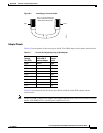
Identifying a Crossover Cable
To identify a crossover cable, compare the two modular ends of the cable. Hold the cable ends
side-by-side, with the tab at the back. The wire connected to the pin on the outside of the left plug should
be the same color as the wire connected to the pin on the outside of the right plug. (See Figure B-7.)
1 TPO+
2 TPO-
3TP1+
6TP1-
1TP1+
Switch Router or PC
2TP1-
3 TPO+
6 TPO-
4TP2+
5TP2-
7TP3+
8TP3-
4TP3+
5TP3-
7TP2+
8TP2-
65272
1 TPO+
2 TPO-
3 TP1+
6 TP1-
1TP0+
Switch Switch
2TP0-
3TP1+
6TP1-
4 TP2+
5 TP2-
7 TP3+
8 TP3-
4TP2+
5TP2-
7TP3+
8TP3-
65274