


2-20
Cisco Catalyst Blade Switch 3040 for FSC Hardware Installation Guide
OL-10694-01
Chapter 2 Blade Switch Installation
Where to Go Next
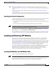
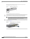
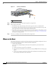
Figure 2-11 Installing an SFP Module
Step 3
Insert the other cable end into a fiber-optic receptacle on a target device.
Step 4 Observe the port status LED.
• The LED turns green when the blade switch and the target device have an established link.
• The LED turns amber while the STP discovers the network topology and searches for loops. This
process takes about 30 seconds, and then the port LED turns green.
• If the LED is off, the target device might not be turned on, there might be a cable problem, or there
might be a problem with the adapter installed in the target device. See Chapter 3, “Troubleshooting,”
for solutions to cabling problems.
Step 5 If necessary, reconfigure and restart the blade switch or target device.
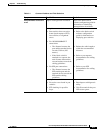
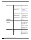
Where to Go Next
If the default configuration is satisfactory, the blade switch does not need further configuration. You can
use any of these management options to change the default configuration:
• Using the Device Manager
Access the device manager through a web browser from anywhere in your network. Follow
these steps:
a. Launch a web browser on your PC or workstation.
b. Enter the blade switch IP address in the web browser, and press Enter. The device manager page
appears.
c. Use the device manager to perform basic blade switch configuration and monitoring. See the
device manager online help for more information.
1 Fiber-optic SFP module
153488
11x
12x
13x
14x
15x
16x
C
o
n
s
ole
11x
12x
13x
14x
15x
16x
C
O
N
ID
1