


B-3
Cisco Catalyst Blade Switch 3040 for FSC Hardware Installation Guide
OL-10694-01
Appendix B Connector and Cable Specifications
Cable and Adapter Specifications
Console Port
The console port uses an 8-pin RJ-45 connector, which is described in Table B-1 and Table B-2. The
supplied RJ-45-to-DB-9 adapter cable is used to connect the console port of the blade switch to a console
PC. You need to provide a RJ-45-to-DB-25 female DTE adapter if you want to connect the blade switch
console port to a terminal. You can order a kit (part number ACS-DSBUASYN=) containing that adapter
from Cisco. For console port and adapter pinout information, see Table B-1 and Table B-2.
Cable and Adapter Specifications
These sections describe the cables and adapters used with the blade switch.
Two Twisted-Pair Cable Pinouts
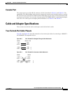
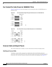
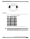
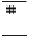
Figure B-3 and Figure B-4 show the schematics of two twisted-pair cables for connecting to 10BASE-T-
and 100BASE-TX-compatible devices.
Figure B-3 Two Twisted-Pair Straight-Through Cable Schematic
Figure B-4 Two Twisted-Pair Crossover Cable Schematic
Switch
3 TD+
6 TD–
1 RD+
2 RD–
Router or PC
3 RD+
6 RD–
1 TD+
2 TD–
H5578
Switch
3 TD+
6 TD–
1 RD+
2 RD–
Switch
3 TD+
6 TD–
1 RD+
2 RD–
H5579