


1-4
Cisco Catalyst Blade Switch 3040 for FSC Hardware Installation Guide
OL-10694-01
Chapter 1 Product Overview
Front Panel Description
LEDs
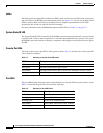
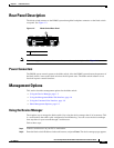
The blade switch has eight LEDs including an LED for each external port, one LED for the console port,
and one LED used by BX600 system management board (see Figure 1-1). You can use the blade switch
LEDs to monitor blade switch activity and performance. Graphical representations of the LEDs
described in this section are visible in the device manager.
For more information about the BX600 management blade LEDS, see Table 2-1 on page 2-5.
System Status/ID LED
The System Status/ID LED is controlled by the BX600 system management blade and is used to identify
a specific blade switch or other component in a rack from the management blade console. You can use
the BX600 system web interface to identify a component, which triggers the specified device to light its
ID LED.
Console Port LEDs
The blade switch console port LED is either green or amber. Table 1-2 describes the console port LED
colors and their meanings.
Port LEDs
The port LEDs display information about each individual port. The port LEDs are green, amber, or both.
Table 1-2 describes the port LED colors and their meanings.
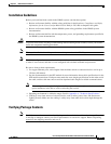
Table 1-1 Meaning of Console Port LED Colors
LED Color Meaning
Off The bootloader is initializing.
Solid green The blade switch console port is active.
Solid amber The blade switch console port is inactive; the backplane console is active.
Solid green or amber Cisco IOS is operating normally.
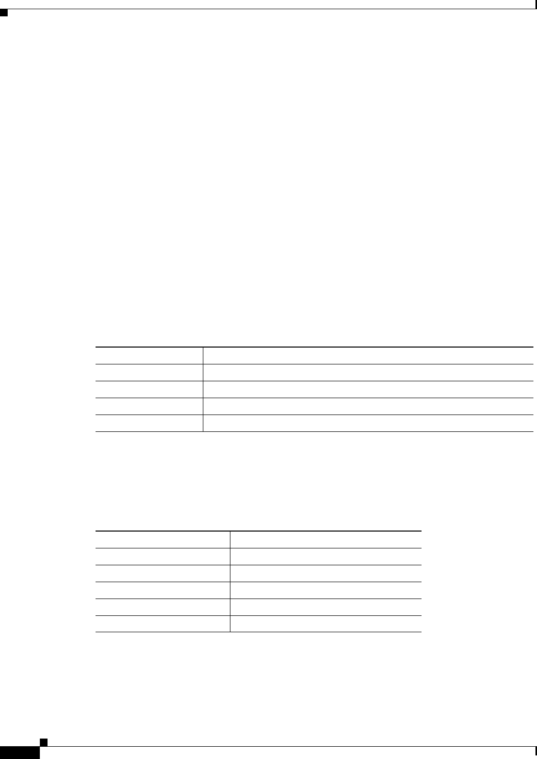
Table 1-2 Meaning of Port LED Colors
LED Color Meaning
Off No link established.
Solid green Link established but no activity.
Blinking green Traffic on an established link.
Solid amber Port disabled, either error or STP
1
disabled.
1. STP = Spanning Tree Protocol
Alternating green and amber Link fault.