


2-9
Installation and Upgrade Guide for Cisco Unified Videoconferencing 3545 PRI Gateway and 3545 Serial Gateway Release 5.6
OL-17011-01
Chapter 2 Installing the Cisco Unified Videoconferencing 3545 Gateway
How to Install the Gateway
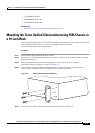
Note If you are installing the gateway module and the power to the chassis is on, the SWAP RDY LED
on the module front panel turns blue when you slide the module into the chassis as far as it will
go. This means that you can secure the module safely. The LED turns off when the handles are
closed.
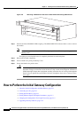
Step 8 Snap the handles forward to secure the gateway module in the slot.
Step 9 Secure the gateway module screws.
Caution Blank faceplates and cover panels serve three important functions: they prevent exposure to
hazardous voltages and currents inside the chassis; they contain electromagnetic interference
(EMI) that might disrupt other equipment; and they direct the flow of cooling air through the
chassis. Do not operate the system unless all cards, faceplates, front covers, and rear covers
are in place.
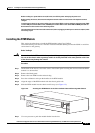
Removing a Module
This section describes how to remove the Cisco Unified Videoconferencing 3545 Gateway or the RTM
module from the Cisco Unified Videoconferencing 3545 chassis.
Before You Begin
Warning
You must remove the gateway module from the slot at the front of the chassis before removing the
corresponding RTM module from the same slot position at the rear of the chassis.
Procedure
Step 1 Loosen the gateway or RTM module screws.
Step 2 Press the red buttons and open the handles of the gateway or RTM module (see Figure 2-6).