


2-16
Installation and Upgrade Guide for Cisco Unified Videoconferencing 3545 PRI Gateway and 3545 Serial Gateway Release 5.6
OL-17011-01
Chapter 2 Installing the Cisco Unified Videoconferencing 3545 Gateway
Serial Gateway Cable Connections and Pin-outs
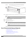
Procedure
Step 1 Connect the DB-60 male connector of the cable to the DB-60 female connector of the unit.
Step 2 Tighten the screws.
Step 3 Connect the remote connectors (V.35, RS-449, EIA-530 and RS-366) to the connectors or the connecting
cable of the remote equipment
Serial Gateway Cable Connections and Pin-outs
• Physical Description of DTE Cables, page 2-16
• Physical Description of DCE Cables, page 2-20
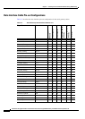
• Data Interface Cable Pin-out Configurations, page 2-22
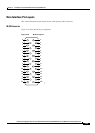
• Data Interface Pin Layouts, page 2-23
• Signaling Interface Cable Pin-out Configuration, page 2-25
• Signaling Interface Pin Layout, page 2-26
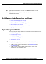
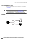
Physical Description of DTE Cables
These are the DTE cables supplied with the Cisco Unified Videoconferencing 3545 Serial Gateway:
• V.35/RS366-DTE, page 2-17
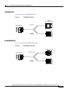
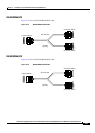
• EIA449/RS366-DTE, page 2-17
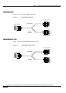
• EIA530/RS366-DTE, page 2-18
• EIA530/RS366-DTE-LOS, page 2-18
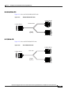
• EIA530A/RS366-DTE, page 2-19
• KIV7/RS366-DTE, page 2-19
Note • The DB-25 connector provides the data interface for the “EIA530/RS366-DTE” and
“EIA530/RS366-DTE-LOS” cables.
• The DB-37 connector provides the data interface for the “EIA449/RS366-DTE” and
“KIV7/RS366-DTE” cables.
• The DB-25 connector provides the RS-366 signaling interface for all Cisco Unified
Videoconferencing 3545 Serial Gateway cables.