


2-25
Installation and Upgrade Guide for Cisco Unified Videoconferencing 3545 PRI Gateway and 3545 Serial Gateway Release 5.6
OL-17011-01
Chapter 2 Installing the Cisco Unified Videoconferencing 3545 Gateway
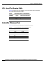
Serial Gateway Cable Connections and Pin-outs
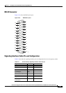
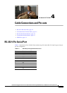
DB-25 Connector
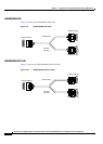
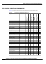
Figure 2-18 shows the DB-25 pin layout.
Figure 2-18 DB-25 Pin Layout
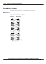
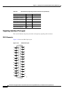
Signaling Interface Cable Pin-out Configuration
Table 2-8 describes the signaling interface pin-out configuration for the serial gateway cables.
1
14
15
16
17
18
19
20
21
22
23
24
25
2
3
4
5
6
7
8
9
10
11
12
13
157145
Table 2-8 Serial Gateway Signaling Interface Cable Pin-out
Signal Name Mnemonic RS-366 (DB-25)
Shield — 1
Digit Present DPR 2
Abandon Call & Retry ACR 3
Call Request CRQ 4
Present Next Digit PND 5
Power Indication PWI 6
Signal Ground — 7
Distant Station
Connection
DSC 13