


1-7
User Guide for the Catalyst Express 520 Switches
OL-12761-02
Chapter 1 Introduction
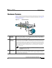
Hardware Features
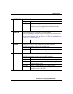
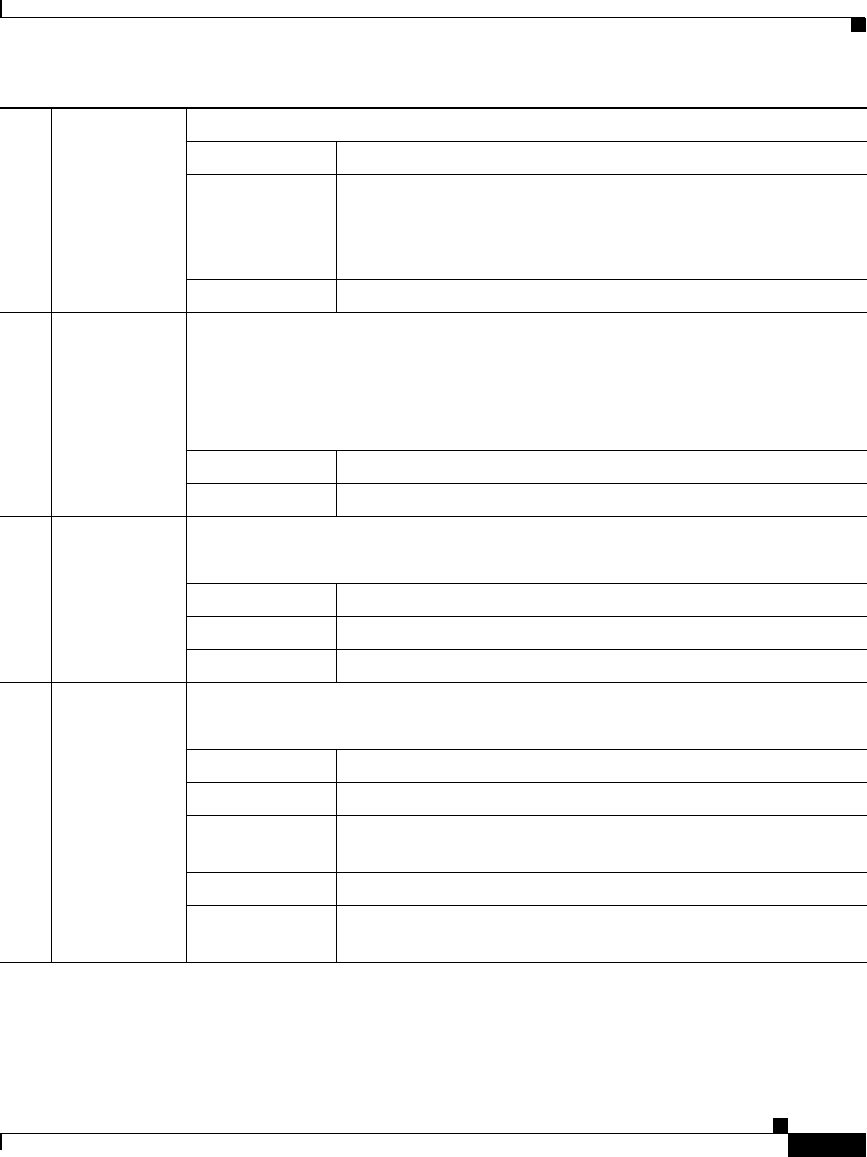
4 SYSTEM LED The SYSTEM LED shows the status of the switch (system).
Solid green Switch is healthy.
Blinking green Switch is running power-on self-test (POST). POST is a series
of tests that runs automatically to ensure that the switch
functions properly. It might take several minutes for the
switch to complete POST.
Solid amber Switch is faulty, is rebooting, or is in recovery.
5ALERT LED The ALERT LED shows the presence of a switch problem.
When the switch detects a problem on one or more ports, the Alert LED turns
amber. The Alert LED stays amber until the Alert Log is cleared. For more
information about the Alert LED and Alert Log, see Table 6-1 and the “Review
the Alert Log” section on page 6-8.
Off (dark) No switch problem is detected.
Solid amber A switch problem is detected.
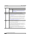
6PoE LED The PoE LED shows the status of PoE being provided to the ports.
This LED is available on switches that have PoE ports.
Off (dark) PoE to the ports is off.
Solid green One or more ports is receiving PoE.
Blinking amber One or more ports is not receiving PoE because of a fault.
7 RPS LED The RPS LED shows the status of a connected redundant power system (RPS).
This LED is available on switches that have an RPS connector.
Off (dark) RPS is off or is not properly connected.
Solid green RPS is connected and is ready to provide back-up power.
Blinking green RPS is connected but is unavailable because it is providing
power to another device.
Solid amber RPS is in standby mode or is in a fault condition.
Blinking amber Switch internal power supply has failed, and the RPS is
providing power to the switch.