


4-3
User Guide for the Catalyst Express 520 Switches
OL-12761-02
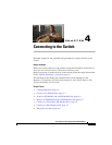
Chapter 4 Connecting to the Switch
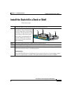
Connect to an Ethernet Port
Connect to an Ethernet Port
Caution To prevent ESD damage, follow your normal board and component handling
procedures.
Caution PoE faults are caused when noncompliant cabling or powered devices are
connected to a PoE port. Only standard-compliant cabling can be used to connect
Cisco pre-standard IP Phones or wireless access points or
IEEE 802.3af-compliant devices to PoE ports. A cable or device that causes a PoE
fault must be removed from the network.
Many legacy powered devices, including older Cisco IP phones and access points
that do not fully support IEEE 802.3af might not support PoE when connected to
the switch by a crossover cable.
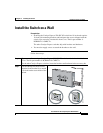
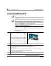
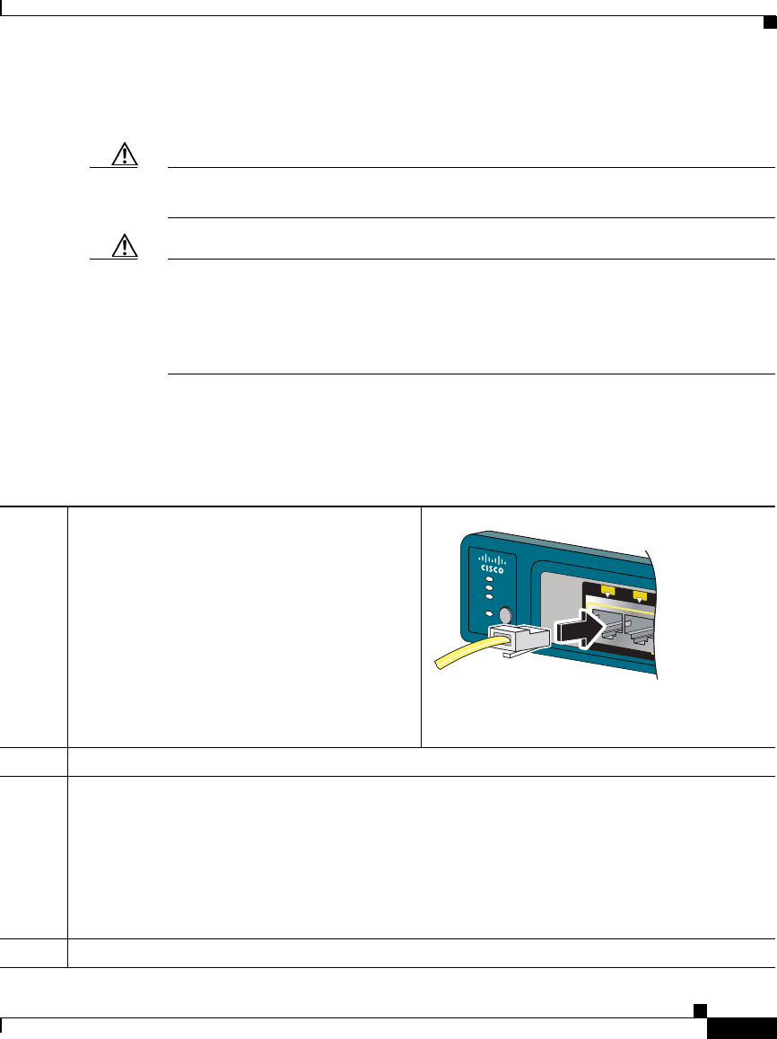
Follow these steps:
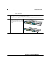
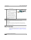
Step 1
Use a straight-through Category 5 cable to
connect a switch 10/100 or 10/100/1000 port
to a desktop, wireless access point, IP phone,
server, printer, or router.
Use a crossover Category 5 cable to connect a
switch port to another switch or a repeater.
Use a twisted four-pair, Category 5 cable to
connect a switch 1000BASE-T small
form-factor pluggable (SFP) module port to
another device.
Step 2
Insert the other cable end in the other device.
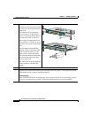
Step 3
Wait until the port LEDs on the switch and the attached device are solid green. The solid green
port LEDs means a successful connection between the two devices.
Troubleshooting:
If the port LEDs are not solid green or if either port LED turns amber, make sure that:
• You are using an undamaged Category 5 Ethernet cable.
• The other device is turned on.
Step 4
Repeat Step 1 to Step 3 as necessary.
SYST
A
L
RT
P
o
E
A
D
M
I
N
POWER
OV
E
R
ETHERNET
1
2
201620