


4-7
User Guide for the Catalyst Express 520 Switches
OL-12761-02
Chapter 4 Connecting to the Switch
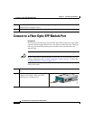
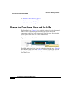
Connect to a Dual-Purpose Port
Connect to a Dual-Purpose Port
Prerequisite
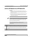
Do not remove the dust plugs from the fiber-optic SFP module port or the rubber
caps from the fiber-optic cable until you are ready to connect the cable. The plugs
and caps protect the SFP module ports and cables from contamination and
ambient light.
Caution Before connecting to the SFP module, be sure that you understand the port and
cabling stipulations in the “Cabling Guidelines” section on page 4-2 and in the
“Cabling Guidelines” section on page A-10.
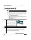
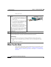
Step 3
Insert the other cable end in the other device.
Step 4
Wait until the port LEDs on the switch and the attached device are solid green. The solid
green port LEDs means a successful connection between the two devices.
Troubleshooting:
If the port LEDs are not solid green or if either port LED turns amber, make sure that:
• You are using an undamaged fiber-optic cable.
• The other device is turned on.