


18
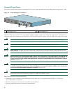
Install the Native Gigabit RJ-45 Ethernet Cables
This section provides information about installing the native Gigabit Ethernet RJ-45 cables.
Intra-Building Lightning Protection
Shielded cables, which are grounded at both ends, are required to be used on the 10/100/1000 Gigabit Ethernet RJ-45 ports in
order to be in compliance with requirement R4-11 in GR-1089-Core for a Central Office environment. This is not a requirement
for customer premises installations.
Warning
To avoid electric shock, do not connect safety extra-low voltage (SELV) circuits to telephone-network voltage
(TNV) circuits. LAN ports contain SELV circuits, and WAN ports contain TNV circuits. Some LAN and WAN ports
both use RJ-45 connectors. Use caution when connecting cables.
Statement 1021
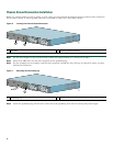
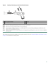
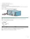
Connect the Cables
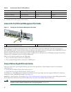
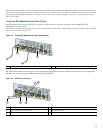
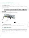
Figure 15 RJ-45 Port and Copper SFP RJ-45 Gigabit Ethernet Port Cabling
Step 1 Insert an Gigabit Ethernet RJ-45 cable into Gigabit Ethernet RJ-45 ports 0/0 and 0/1 if you are not using Gigabit
Ethernet SFP optical ports 0/0 and 0/1.
Step 2 Insert an Gigabit Ethernet RJ-45 cable into a copper SFP module in Gigabit Ethernet ports 0/2 and 0/3.
.
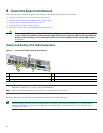
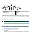
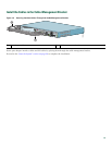
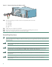
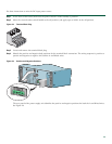
Connect the Port Adapter Cables
The instructions for connecting the cables for the port adapter installed in the Cisco 7201 router are contained in the respective
configuration notes for each port adapter. For example, if you are connecting the optical fiber cables for the PA-GE port adapter,
refer to the PA-GE Gigabit Ethernet Port Adapter Installation and Configuration document at
http://www.cisco.com/en/US/docs/interfaces_modules/port_adapters/install_upgrade/ethernet/pa-ge_gigabit_ethernet_install_c
onfig/pa_ge.html.
Port adapter documents are also available on the Cisco Documentation DVD.
1 RJ-45 connector 2 Copper SFP module
230316
GE 0/0
GE 0/1
GE 0/2
GE 0/3
AUX
CONSOLE
MNGMNT USE ONLY
FE
LINK
0
FE 0/0
RJ45
SFP
SFP
SFP
SFP
LINK/ACTV
LINK/ACTV
RX
TX
LINK/ACTV
LINK/ACTV
RX
TX
EN
RJ45
EN
Cisco
7201
1
2