


29
Start the Router
Check the following conditions before you start your router:
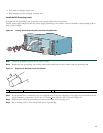
• The port adapter is inserted in its slot and the port adapter lever is in the locked position.
• The network interface cable is connected to the port adapter.
• A CompactFlash Disk is installed.
• SFP modules and their optical-fiber or copper cables are installed.
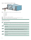
• The optional USB Flash memory module or Aladdin eToken Pro key is installed.
• The optional Fast Ethernet Management port cable is installed.
• The console terminal is turned on.
Step 1 Place the power switch in the on (O) position.
Step 2 Listen for the fans; they should be operating as soon as power is turned on. The following table provides information
about the LEDs as the system starts.
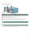
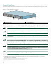
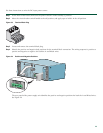
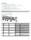
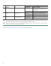
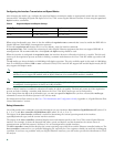
Figure 30 Cisco 7201 Router—Faceplate LEDs
No. LED Label LED
In the Power Up State
Color-Activityr Behavior Description
1
LINK/ACTV
(Link/Active) (0/0, 0/1,
0/2, 0/3)
SFP and RJ-45 ports Solid green Link with no activity
Flashing green Link with activity
Off No link
2
EN (Enable) (0/0, 0/1) RJ-45 ports only Solid green RJ-45 port is selected.
Off SFP port is selected.
3
USB USB port Flashing green Activity
Off No activity
4
FE 0/0 Fast Ethernet Management
port
Solid green Link with no activity
Flashing green Link with activity
Off No link
5
ALARM Alarm port Solid red
On if Cisco IOS has crashed, and a reset
has happened, and remains on until Cisco
IOS is reloaded.
Off Off, the system is normal.
GE 0/0
GE 0/1
GE 0/2
GE 0/3
AUX
CONSOLE
MNGMNT USE ONLY
FE
LINK
0
FE 0/0
RJ45
SFP
SFP
SFP
SFP
LINK/ACTV
ALARM
PW
R OK
STATUS
CF
ACTV
COMPACT FLASH
LINK/ACTV
RX
TX
LINK/ACTV
LINK/ACTV
RX
TX
EN
RJ45
EN
170859
5
6
7
8
1
2
1
2
1
1
3
4
Cisco
7201