


3
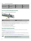
2 Prepare for Installation
This section contains information about tools and parts, warnings, site preparation information, and information for
workbench or tabletop installation and rack-mount installation.
Warning
Only trained and qualified personnel should be allowed to install, replace, or service this equipment.
Statement
1030
Warning
The ports labeled “Ethernet,” “10BaseT,” “Token Ring,” “Console,” and “AUX” are safety extra-low voltage (SELV)
circuits. SELV circuits should only be connected to other SELV circuits. Because the BRI circuits are treated like
telephone-network voltage, avoid connecting the SELV circuit to the telephone network voltage (TNV) circuits.
Statement 22
Before beginning this router installation, read the Regulatory Compliance and Safety Information for Cisco 7200 Series Routers
document.
Site Preparation and Unpacking
• Lift the router safely out of the packing container.
• Ensure the power service at the site is suitable for the router you are installing.
• Check the packing slip to ensure that all the proper components are present.
• Locate and have accessible the Site Log for recording information about this installation.
Tools and Parts
Use the following list of tools and parts as a checklist for preparing to install the Cisco 7201 router:
• ESD-preventative wrist strap
• Power cord
• Appropriate cables to connect the router to the network, console port, and auxiliary port
• Tape measure and level (optional)
• Screwdrivers: Number 2 Phillips screwdriver and 3/16-inch flat-blade screwdriver
• Wire stripper
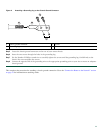
• Chassis grounding lug and wires:
–
A grounding lug with two number-10 screw holes with a 0.63-inch (16.002-mm) spacing between them
–
A wire receptacle large enough to accept a 6-AWG multistrand, copper wire
–
Two Phillips machine screws with locking washers—M5 (metric), 0.031-inch (.08-mm) pitch, 0.315-inch (8-mm) length
–
A crimping tool to fit the grounding lug wire receptacle
–
One grounding wire—6-AWG, 0.162-inch (4.115-mm) diameter, with approximately 0.108-inch (2.743-mm)
insulation, for a total wire diameter of approximately 0.27 inches (6.858 mm). The wire length depends on your router
location and site environment.
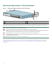
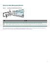
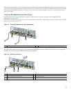
• The rack-mount and cable-management kit:
–
Two rack-mount brackets and one cable-management bracket
–
Screws: Four 6-32 x 0.25-inch screws, two M3 x 8-mm screws, four 10-32 or 12-24 screws, and one M4 x 20-mm screw