


26
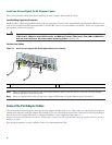
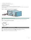
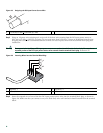
Figure 25 Stripping the DC-Input Power Source Wire
Step 5 Using an 18-gauge wire-stripping tool, strip each of the four wires coming from the DC-input power source to
0.25 inch (6.3 mm) +
0.02 inch (0.5 mm). Do not strip more than 0.29 inch (7.4 mm) of insulation from the wire.
Stripping more than the recommended amount of wire can leave exposed wire from the terminal block plug after
installation.
Warning
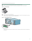
An exposed wire lead from a DC-input power source can conduct harmful levels of electricity. Be sure that no
exposed portion of the DC-input power source wire extends from the terminal block plug.
Statement 122
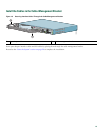
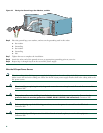
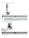
Figure 26 Inserting Wires into the Terminal Block Plug
Step 6 Insert the exposed wire of one of the four DC-input power source wires into the terminal block plug, as shown in
Figure 26. Make sure that you cannot see any wire lead. Only wire with insulation should extend from the terminal
block.
1 0.25 inch (6.3 mm) + 0.02 inch (0.5 mm)
1 Negative( –) 3 Negative (–)
2 Return (+) 4 Return (+)
57019
1
170975
A
B
1
2
3
4