


45
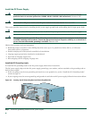
For general information about SFP modules, see the Chapter 4 of the Cisco 7201 Installation and Configuration Guide, the
“Removing and Installing an SFP Module” section.
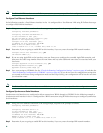
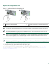
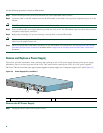
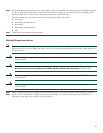
Figure 33 Optical SFP Module and Copper SFP Module
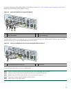
The optical SFP modules can occupy any of the four optical Gigabit Ethernet ports, 0/0 through 0/3. However, the copper SFP
modules can occupy only optical Gigabit Ethernet ports 0/2 and 0/3.
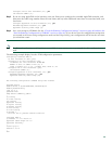
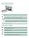
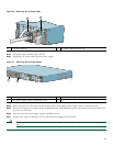
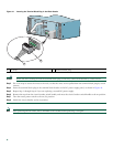
Figure 34 Inserting an SFP Module into the Cisco 7201 Gigabit Ethernet Port 0/1
Use the following procedure to remove an SFP module:
Step 1 Attach an ESD-preventive wrist strap between you and an unpainted chassis surface.
Step 2 Make sure there is no traffic flowing through the native Gigabit Ethernet port.
Step 3 Remove the optical fiber cable, taking care not to touch the connector.
Step 4 Pull gently to detach the SFP module from the chassis.
Step 5 Insert a plug into the SFP module.
1 Optical SFP module plug 3 Copper SFP module RJ-45 connector
2 Optical SFP module 4 Copper SFP module
1 Gigabit Ethernet port 0/1—SFP port 2 SFP module
230304
GE 0/0
GE 0/1
GE 0/2
GE 0/3
AUX
CONSOLE
MNGMNT USE ONLY
FE
LINK
0
FE 0/0
RJ45
SFP
SFP
SFP
SFP
LINK/ACTV
LINK/ACTV
RX
TX
LINK/ACTV
LINK/ACTV
RX
TX
EN
RJ45
EN
T
X
R
X
Cisco 7201
1 2
3 4
170860
GE 0/0
GE 0/1
GE 0/2
GE 0/3
AUX
CONSOLE
MNGMNT USE ONLY
FE
LINK
0
FE 0/0
RJ45
SFP
SFP
SFP
SFP
LINK/ACTV
LINK/ACTV
RX
TX
LINK/ACTV
LINK/ACTV
RX
TX
EN
RJ45
EN
2
1
T
X
R
X
Cisco 7201