


6
Attach the Rack-Mount Brackets—Chassis Rear-Mounted
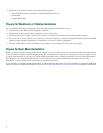
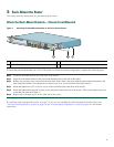
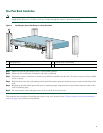
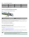
Figure 2 Attaching the Rack-Mount Brackets to the Rear of the Chassis
To install the rack-mount brackets on a Cisco 7201 router for a rear rack-mount configuration, complete the following steps:
Step 1 Locate the threaded holes in the rear sides of the chassis.
Step 2
Align the rack-mount bracket to the rack-mount bracket holes on the side of the router.
Step 3
Remove any existing cover screws from the sides of the chassis that align with the rack-mount bracket holes and then
realign the bracket. (You should have to remove one cover screw from each side of the chassis.)
Step 4 Insert and tighten two 6-32 x 0.25-in. screws in the two holes nearest the rear of the chassis.
Step 5 Insert and tighten the longer M3 x 8-mm screw in the hole nearest the front of the chassis. (This screw replaces the cover
screw that you removed in Step 3.)
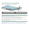
Step 6 Repeat Step 1 through Step 5 on the other side of the router.
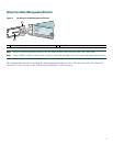
To install the cable-management bracket, see page 7. If you are not installing the cable-management bracket, skip to the
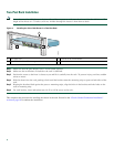
“Two-Post Rack Installation” section on page 8 or the “Four-Post Rack Installation” section on page 9 for rack-mount
instructions.
1
Rack-mount bracket
3
Two M3 x 8-mm screws
2
Four 6-32 x 0.25-in. screws
281125
ENABLED
R
X
C
E
L
L
S
R
X
C
A
R
R
IE
R
R
X
A
L
A
R
M
A
TM
G
E
0
/0
G
E
0
/1
G
E
0
/2
G
E
0
/3
A
U
X
C
O
N
S
O
L
E
M
N
G
M
N
T
U
S
E
O
N
L
Y
F
E
L
IN
K
0
F
E
0
/0
R
J
4
5
S
F
P
S
F
P
S
F
P
S
F
P
L
IN
K
/A
C
T
V
A
L
A
R
M
P
W
R
O
K
S
T
A
T
U
S
C
F
A
C
T
V
C
O
M
P
A
C
T
FL
A
SH
L
IN
K
/A
C
T
V
R
X
T
X
L
IN
K
/A
C
T
V
L
IN
K
/A
C
T
V
R
X
T
X
E
N
R
J
4
5
E
N
P
A
S
L
O
T
1
2
1
3
Cisco 7201