


7
Install the Hardware
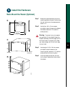
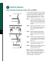
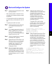
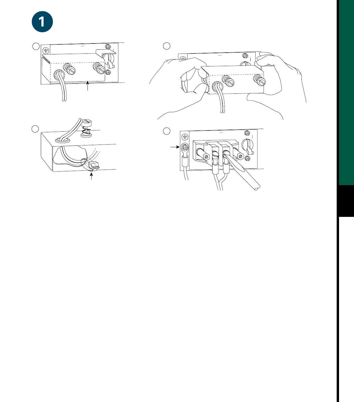
Caution: Do not strain the connection at the terminal block
53422
Terminal block
cover and
captive screws
-48/-60V
20/16A
—
RTN
-48
POWER SUPPLY
TERM. BLOCK COVER
- USE ONLY WITH
NEC CLASS 3
WIRING
- USE COPPER
CONDUCTORS
-48/-60V
20/16A
—
RTN
-48
-48/-60V
20/16A
—
RTN
-48
POWER SUPPLY
TERM. BLOCK COVER
- USE ONLY WITH
NEC CLASS 3
WIRING
- USE COPPER
CONDUCTORS
Cable strain relief
nylon cable tie
A
B
D
C
Ground
terminal
Step 2 Loosen the two captive screws that secure
the terminal block cover, as shown in A.
Step 3 Pull the terminal block cover away from
the terminal block, as shown in B.
Step 4 Feed the return (RTN) and –48V wires
through the large hole in the terminal
block cover, as shown in C.
Step 5 Attach a nylon cable tie to secure the
cables to the terminal block cover.
Step 6 Attach the RTN and –48 leads to the
terminal block, as shown in C.
Note Match the color coding at the DC source.
Typically, green or green/yellow is used for ground,
black is used for RTN, and red or white is used for
–48V.
Step 7 Attach the ground cable to the ground
terminal.
Step 8 Replace the terminal block cover, as
shown in B.
Step 9 Tighten the captive screws on the terminal
block cover, as shown in A.