


1-9
Catalyst 3560 Switch Hardware Installation Guide
OL-6337-03
Chapter 1 Product Overview
Front Panel Description
• 100BASE-FX
• CWDM
For more information about these SFP modules, see your SFP module documentation.
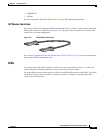
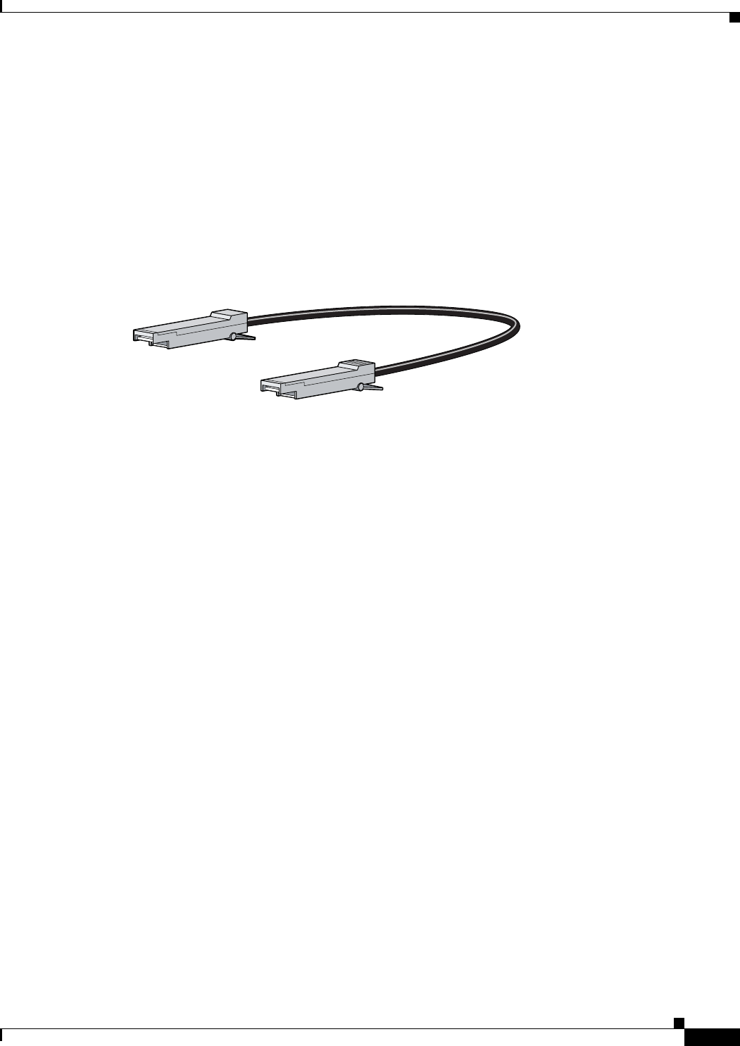
SFP Module Patch Cable
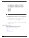
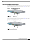
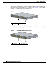
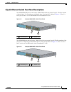
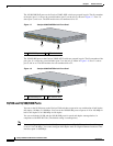
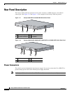
The Catalyst 3560 switch supports the SFP module patch cable, a 1/2 meter, copper, passive cable with
SFP module connectors at each end (see Figure 1-9). The patch cable can connect two Catalyst 3560
switches in a cascaded configuration.
Figure 1-9 SFP Module Patch Cable
See “Inserting and Removing the SFP Module Patch Cable” section on page 2-18 for more information
about using the SFP module patch cable.
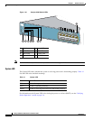
LEDs
You can use the switch LEDs to monitor switch activity and its performance. Figure 1-10 shows the
switch LEDs and the Mode button that you use to select one of the port modes.
All of the LEDs described in this section are visible in the CMS and Network Assistant GUIs. The switch
online help describes how to use CMS or Network Assistant to configure and monitor individual
switches and switch clusters.
126809