


2-15
Catalyst 3560 Switch Hardware Installation Guide
OL-6337-03
Chapter 2 Switch Installation
Installing and Removing SFP Modules
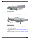
Table- or Shelf- Mounting
Follow these steps to install the switch on a table or shelf:
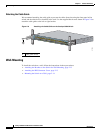
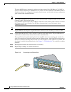
Step 1 Locate the adhesive strip with the rubber feet in the mounting-kit envelope. Attach the four rubber feet
on the bottom of the switch near the four corners.
Note Do not attach the rubber feet over the recessed screw holes on the bottom of the switch.
Step 2 Place the switch on the table or shelf near an AC power source.
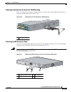
After the switch is mounted in the rack, you need to do these tasks to complete the installation:
• Power on the switch. See the “Verifying Switch Operation” section on page 2-6.
• Connect to a 10/100 or 10/100/1000 port and run Express Setup. See the Catalyst 3560 Switch
Getting Started Guide for instructions.
• Connect to the front-panel ports. See the “Connecting to the 10/100 or 10/100/1000 Ports” section
on page 2-19 and the “Connecting to SFP Modules” section on page 2-21 to complete the
installation.
For configuration instructions about using the CLI setup program, go to Appendix C, “Configuring the
Switch with the CLI-Based Setup Program.”
Note When the connectors are not being used, replace the dust covers on them for protection.
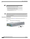
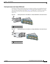
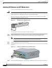
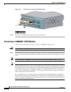
Installing and Removing SFP Modules
These sections describe how to install and remove SFP modules. The modules are inserted into the SFP
module slots on the front of the Catalyst 3560 switches. These field-replaceable modules provide uplink
interfaces.
You can use any combination of SFP modules. See the Catalyst 3560 release notes for the list of SFP
modules that the Catalyst 3560 switches support. Each port must match the wave-length specifications
on the other end of the cable, and for reliable communications, the cable must not exceed the stipulated
cable length. See the “Installation Guidelines” section on page 2-4 for cable stipulations for SFP
connections.
Use only Cisco SFP modules on the Catalyst 3560 switch. Each SFP module has an internal serial
EEPROM that is encoded with security information. This encoding provides a way for Cisco to identify
and validate that the SFP module meets the requirements for the switch.
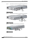
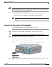
For detailed instructions on installing, removing, and cabling the SFP module, see the SFP module
documentation.