


2-11
Catalyst 3560 Switch Hardware Installation Guide
OL-6337-03
Chapter 2 Switch Installation
Installing the Switch
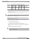
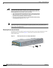
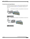
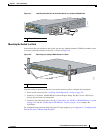
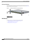
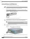
Figure 2-7 Attaching Brackets for 24-Inch Telco Racks to a Catalyst 3560 Switch
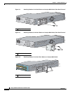
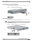
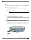
Mounting the Switch in a Rack
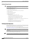
After the brackets are attached to the switch, use the four supplied number-12 Phillips machine screws
to securely attach the brackets to the rack, as shown in Figure 2-8.
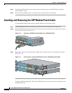
Figure 2-8 Mounting the Catalyst 3560 Switch in a Rack
After the switch is mounted in the rack, you need to do these tasks to complete the installation:
• Power on the switch. See the “Verifying Switch Operation” section on page 2-6.
• Connect to a 10/100 or 10/100/1000 port and run Express Setup. See the Catalyst 3560 Switch
Getting Started Guide for instructions.
• Connect to the front-panel ports. See the “Connecting to the 10/100 or 10/100/1000 Ports” section
on page 2-19 and the “Connecting to SFP Modules” section on page 2-21 to complete the
installation.
For configuration instructions about using the CLI setup program, go to Appendix C, “Configuring the
Switch with the CLI-Based Setup Program.”
1 Phillips flat-head screws
40
41
42
43
44
45
46
47
48
4
7
X
4
8
X
97922
Catalyst 3560
SERIES
P
o
E
-4
8
1
2
3
4
1
1 Phillips machine screws
C
a
ta
ly
st 3
5
6
0
S
E
R
I
E
S
P
o
E
-4
8
S
Y
S
T
R
P
S
S
T
A
T
D
U
P
L
X
S
P
E
E
D
P
o
E
M
O
D
E
1
2
3
4
1
2
5
6
7
8
9
1
0
1
1
1
2
1
3
1
4
1
5
1
6
3
4
1
X
2
X
1
5
X
1
6
X
1
7
1
8
2
1
2
2
2
32
4
2
5
2
6
2
72
8
2
9
3
0
3
1
3
2
1
9
2
0
1
7
X
1
8
X
3
1
X
3
2
X
3
3
3
4
3
7
3
8
3
9
4
0
4
1
4
2
4
3
4
4
4
5
4
6
4
7
4
8
3
5
3
6
3
3
X
3
4
X
4
7
X
4
8
X
97923
1