


2-20
Catalyst 3560 Switch Hardware Installation Guide
OL-6337-03
Chapter 2 Switch Installation
Connecting to the 10/100 or 10/100/1000 Ports
The Auto-MDIX feature is enabled by default on switches running Cisco IOS Release 12.2(18)SE or
later. For releases between Cisco IOS Release 12.1(14)EA1 and 12.2(18)SE, the Auto-MDIX feature is
disabled by default. For configuration information for this feature, see the switch software configuration
guide or the switch command reference.
Note The Catalyst 3560 switch can connect to a Cisco IP Phone through a straight-through, twisted four-pair
Category 5 cable. The rear panel of the
Cisco IP Phone might have more than one RJ-45 connector. Use the LAN-to-phone connector to connect
the IP phone to the switch. See the Cisco IP Phone documentation for more information about
connecting devices to it.
Note Many legacy powered devices, including older Cisco IP phones and access points that do not fully
support IEEE 802.3af, might not support PoE when connected to the switches by a crossover cable.
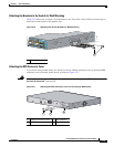
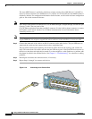
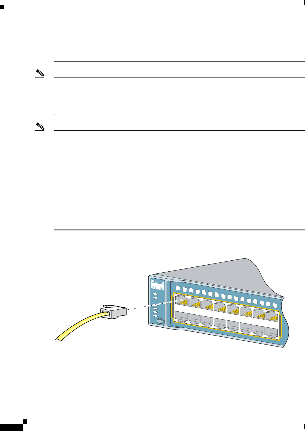
Step 2 Connect the other end of the cable to an RJ-45 connector on the other device. The port LED turns on
when both the switch and the connected device have established link.
The port LED is amber while Spanning Tree Protocol (STP) discovers the topology and searches for
loops. This takes about 30 seconds, and then the port LED turns green. If the port LED does not turn on,
the device at the other end might not be turned on, or there might be a cable problem or a problem with
the adapter installed in the attached device. See Chapter 3, “Troubleshooting,” for solutions to cabling
problems.
Step 3 Reconfigure and reboot the connected device, if necessary.
Step 4 Repeat Steps 1 through 3 to connect each device.
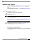
Figure 2-18 Connecting to an Ethernet Port
SYST
RPS
STAT
DUPLX
SPEED
PoE
MODE
1
2
5
6
7
8
9
10
11
12
13
14
15
16
3
4
1
X
2
X
1
5
X
1
6
X
97930