


B-4
Catalyst 3560 Switch Hardware Installation Guide
OL-6337-03
Appendix B Connector and Cable Specifications
Cable and Adapter Specifications
Cable and Adapter Specifications
These sections describe the cables and adapters used with Catalyst 3560 switches.
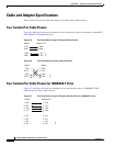
Two Twisted-Pair Cable Pinouts
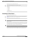
Figure B-5 and Figure B-6 show the schematics of two twisted-pair cables for connecting to 10BASE-T-
and 100BASE-TX-compatible devices.
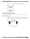
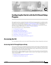
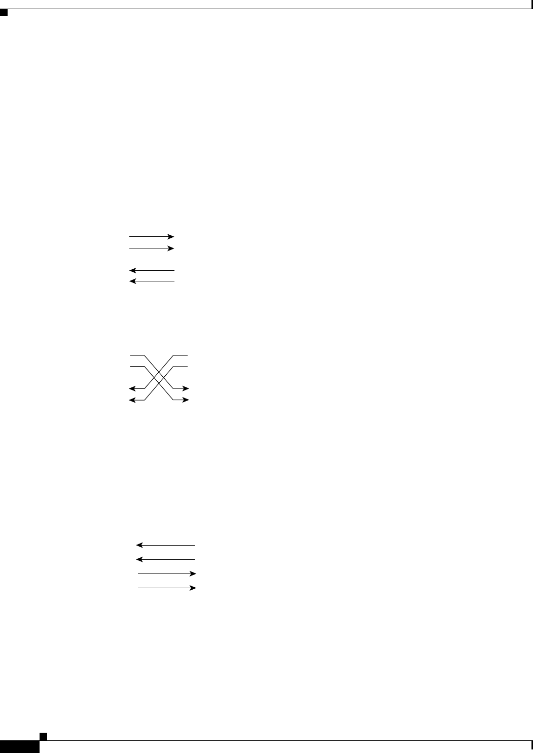
Figure B-5 Two Twisted-Pair Straight-Through Cable Schematic
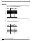
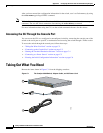
Figure B-6 Two Twisted-Pair Crossover Cable Schematic
Four Twisted-Pair Cable Pinouts for 1000BASE-T Ports
Figure B-7 and Figure B-8 show the schematics of four twisted-pair cables for 1000BASE-T SFP
module ports on Catalyst 3560 switches.
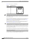
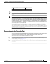
Figure B-7 Four Twisted-Pair Straight-Through Cable Schematic for 1000BASE-T Ports
Switch
3 TD+
6 TD–
1 RD+
2 RD–
Router or PC
3 RD+
6 RD–
1 TD+
2 TD–
H5578
Switch
3 TD+
6 TD–
1 RD+
2 RD–
Switch
3 TD+
6 TD–
1 RD+
2 RD–
H5579
1 RD+
2 RD-
3TD+
6TD-
1 TD+
Switch Router or PC
2 TD-
3 RD+
6 RD-
4NC
5NC
7NC
8NC
4NC
5NC
7NC
8NC
65271