


B-2
Catalyst 3560 Switch Hardware Installation Guide
OL-6337-03
Appendix B Connector and Cable Specifications
Connector Specifications
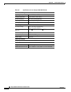
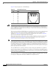
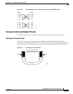
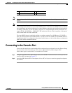
Figure B-2 shows the pinout for a 10/100/1000 port.
Figure B-2 10/100/1000 Port Pinouts
Caution PoE faults are caused when noncompliant cabling or powered devices are connected to a PoE port. Only
standard-compliant cabling can be used to connect Cisco pre-standard IP Phones or wireless access
points or IEEE 802.3af-compliant devices to PoE ports. A cable or device that causes a PoE fault must
be removed from the network.
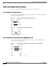
When connecting 10/100 and 10/100/1000 ports to compatible devices such as servers, workstations, and
routers, you can use a two or four twisted-pair straight-through cable wired for 10BASE-T and
100BASE-TX. Figure B-5 shows the two twisted-pair straight-through cable schematics. Figure B-7
shows the four twisted-pair straight-through cable schematics.
When connecting the ports to other devices, such as switches or repeaters, you can use a two or four
twisted-pair crossover cable. Figure B-6 shows the two twisted-pair crossover cable schematics.
Figure B-8 shows the four twisted-pair crossover cable schematics.
Note You can use the mdix auto interface configuration command in the CLI to enable the automatic
medium-dependent interface crossover (Auto-MDIX) feature. When the Auto-MDIX feature is enabled,
the switch detects the required cable type for copper Ethernet connections and configures the interfaces
accordingly. Therefore, you can use either a crossover or a straight-through cable for connections to a
copper 10/100, 10/100/1000, or 1000BASE-T SFP module port on the switch, regardless of the type of
device on the other end of the connection.
The Auto-MDIX feature is enabled by default on switches running Cisco IOS Release 12.2(18)SE or
later. For releases between Cisco IOS Release 12.1(14)EA1 and 12.2(18)SE, the Auto-MDIX feature is
disabled by default. For configuration information for this feature, see the switch software configuration
guide or the switch command reference.
You can use Category 3, 4, or 5 cabling when connecting to 10BASE-T-compatible devices. You must
use Category 5 cabling when connecting to 100BASE-TX-compatible devices.
60915
231 45678Pin Label
1
2
3
4
5
6
7
8
TP0+
TP0-
TP1+
TP2+
TP2-
TP1-
TP3+
TP3-