


3-28
Cisco IOS XR Getting Started Guide
OL-10957-02
Chapter 3 Bringing Up the Cisco IOS XR Software on a Multishelf System
Bringing Up and Configuring Rack 0
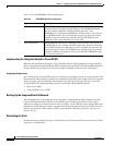
Interface Role Sts Cost Prio.Nbr Type
---------------- ---- --- --------- -------- ----------------------------
FE_Port_1 Desg FWD 200000 128. 2 P2p
GE_Port_0 Root FWD 20000 128. 49 P2p
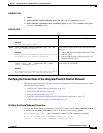
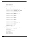
To verify STP information for inter-rack switches, use the show controllers switch inter-rack ports
command, as shown in the following example:
RP/0/RP0/CPU0:router(admin)# show controllers switch inter-rack stp location f0/sc0/cpu0
##### MST 0 vlans mapped: 2-4094
Bridge address 5246.48f0.20ff priority 32768 (32768 sysid 0)
Root this switch for the CIST
Operational hello time 1, forward delay 6, max age 8, txholdcount 6
Configured hello time 1, forward delay 6, max age 8, max hops 4
Interface Role Sts Cost Prio.Nbr Type
---------------- ---- --- --------- -------- ---------------------------
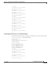
##### MST 1 vlans mapped: 1
Bridge address 5246.48f0.20ff priority 32769 (32768 sysid 1)
Root this switch for MST1
Interface Role Sts Cost Prio.Nbr Type
---------------- ---- --- --------- -------- ---------------------------
GE_13 Desg FWD 20000 128. 14 P2p
GE_14 Desg FWD 20000 128. 15 P2p
GE_15 Desg FWD 20000 128. 16 P2p
GE_17 Desg FWD 20000 128. 18 P2p
GE_22 Desg FWD 20000 128. 23 P2p
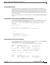
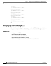
Bringing Up and Configuring Rack 0
When the control network has been established by installing, cabling, and configuring the Catalyst
switches, it is time to bring up and configure Rack 0 in the multishelf system, as described in the
following procedure.
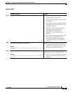
SUMMARY STEPS
1. Power down all LCCs and FCCs.
2. Apply power to the LCC that contains the DSC.
3. Connect to the DSC console port and log in.
4. admin
5. configure
6. dsc serial serial ID rack 0
7. dsc serial serial ID rack rackNumber
8. dsc serial serial ID rack Fn
9. commit
10. show running-config | include dsc