


3-45
Cisco IOS XR Getting Started Guide
OL-10957-02
Chapter 3 Bringing Up the Cisco IOS XR Software on a Multishelf System
Verifying Fabric Cabling Connections
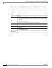
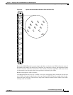
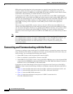
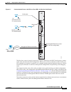
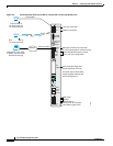
Figure 3-5 Optical Interface Module LED Panel (Part CRS-FCC-LED)
Because the OIM LED panel is present only in the fabric card chassis, the LEDs indicate the status of
the bundles in the fabric card chassis only. Therefore, if a connection is wrong, the equipment assumes
that the connection at the line card chassis is fixed, and the connection at the fabric card chassis is the
one that needs to be relocated to the correct position as indicated by the LEDs.
Bundles are mapped to LEDs as follows:
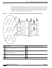
The OIM LED panel has 9 rows of 12 LEDs— the 9 rows correspond to the 9 connectors for each slot,
and 12 LEDs correspond to the 12 slots in the cage. Separate OIM LED panels provide status for the
upper and lower card cages. The LED rows map to the connector number, and the LEDs in each LED
row map to the slot number.
0
1
2
3
4
5
6
7
8
9
10
11
0
1
2
3
4
5
6
7
8
9
10
11
J0
0
1
2
3
4
5
6
7
8
9
10
11
J1
0
1
2
3
4
5
6
7
8
9
10
11
J2
0
1
2
3
4
5
6
7
8
9
10
11
J3
0
1
2
3
4
5
6
7
8
9
10
11
J4
0
1
2
3
4
5
6
7
8
9
10
11
J5
0
1
2
3
4
5
6
7
8
9
10
11
J6
0
1
2
3
4
5
6
7
8
9
10
11
J7
J8
129913
0
1
2
3
4
5
6
7
8
9
10
11
J0