


3-40
Cisco IOS XR Getting Started Guide
OL-10957-02
Chapter 3 Bringing Up the Cisco IOS XR Software on a Multishelf System
Verifying the Spanning Tree
Examples
This section contains examples for the following subjects:
• Verify That the FCCs and Non-DSC LCC Are Communicating with the DSC, page 3-40
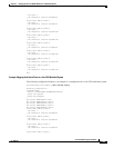
• Verify the Spanning Tree, page 3-41
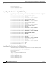
Verify That the FCCs and Non-DSC LCC Are Communicating with the DSC
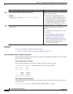
In the following EXEC mode example, all modules are displayed and the state for all modules is
“IOS XR RUN.”
RP/0/RP0/CPU0:router# admin
RP/0/RP0/CPU0:router(admin)# show platform
Node Type PLIM State Config State
-----------------------------------------------------------------------------
0/3/SP MSC(SP) N/A IOS XR RUN PWR,NSHUT,MON
0/3/CPU0 MSC 16OC48-POS/DPT IOS XR RUN PWR,NSHUT,MON
0/RP0/CPU0 RP(Active) N/A IOS XR RUN PWR,NSHUT,MON
0/RP1/CPU0 RP(Standby) N/A IOS XR RUN PWR,NSHUT,MON
0/FC0/SP LCC-FAN-CT(SP) N/A IOS XR RUN PWR,NSHUT,MON
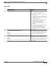
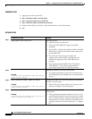
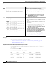
Step 2
show platform
Example:
RP/0/RP0/CPU0:router(admin)# show platform
Displays the status of all hardware components.
• The state for all modules should be IOS XR RUN or
OK.
• It can take a few minutes for all LCC modules to start
up.
Note To view the status of all cards and modules, the
show platform command must be executed in
administration EXEC mode.
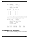
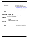
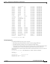
Step 3
show spantree mst 1 detail location
rack
/
slot
/cpu0
Example:
RP/0/RP0/CPU0:router(admin)# show spantree mst
1 detail location 0/rp0/cpu0
RP/0/RP0/CPU0:router(admin)# show spantree mst
1 detail location 0/rp1/cpu0
RP/0/RP0/CPU0:router(admin)# show spantree mst
1 detail location 1/rp0/cpu0
RP/0/RP0/CPU0:router(admin)# show spantree mst
1 detail location 1/rp1/cpu0
RP/0/RP0/CPU0:router(admin)# show spantree mst
1 detail location F0/SC0/cpu0
RP/0/RP0/CPU0:router(admin)# show spantree mst
1 detail location F0/SC1/cpu0
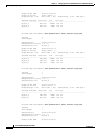
Verifies the spanning tree.
• Enter this command for each RP and SCGE card in the
system.
• The output for each RP and SCGE card should display
the following:
–
In the Switched Interface column, one GE port
should be in the forwarding (FWD) state.
–
Each RP and SCGE card should display the same
designated root MAC address.
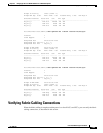
• Verify that the designated root address matches the
expected Catalyst switch, as defined by the Catalyst
switch configuration. The root address should be the
switch with the lowest priority number (0).
• For more information to configure and verify the
external Catalyst switches, see the “Verifying the
Catalyst Switch” section on page 3-18.
Command or Action Purpose