


1-12
Cisco IE 2000 Switch Hardware Installation Guide
OL-25818-04
Chapter 1 Product Overview
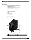
Front Panel
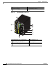
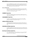
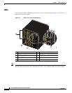
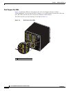
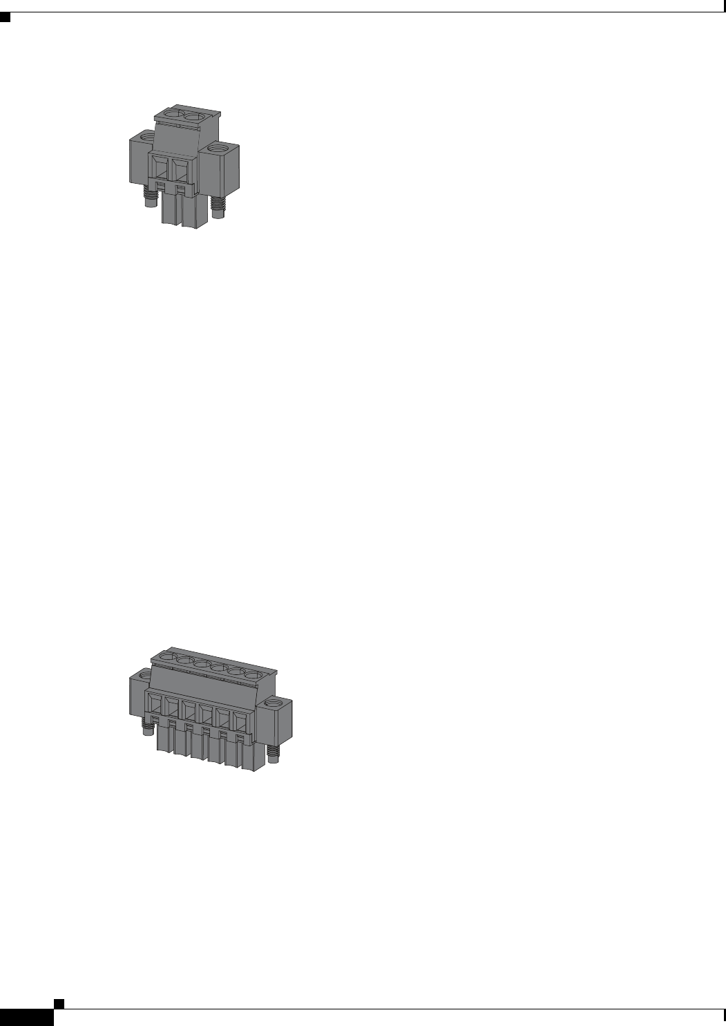
Figure 1-5 Power Connector
The switch can operate with a single power source or with dual power sources. When both power sources
are operational, the switch draws power from the DC source with the higher voltage. If one of the two
power sources fail, the other continues to power the switch.
PoE Power Connector
The IE 2000 switch models with PoE capability (IE-2000-16PTC-G-E, IE-2000-16PTC-G-L, and IE-
2000-16PTC-G-NX) are equipped with an additional DC input terminal block. This DC terminal block
allows the connection of a second power supply (see the “Power over Ethernet Ports” section on page 1-
9), or a second input from site source DC power to operate the PoE ports. The PoE terminal block accepts
48 VDC or 54 VDC at 2.5 A.
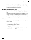
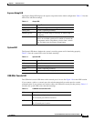
Alarm Connector
You connect the alarm signals to the switch through the alarm connector. The switch supports two alarm
inputs and one alarm output relay. The alarm connector is on the bottom right of the front panel. See
Figure 1-2.
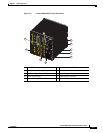
The alarm connector provides six alarm wire connections. The connector is attached to the switch front
panel with the provided captive screws.
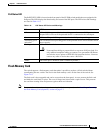
Figure 1-6 Alarm Connector
Both alarm input circuits can sense if the alarm input is open or closed. The alarm inputs can be activated
for environmental, power supply, and port status alarm conditions. From the CLI, you can configure each
alarm input as an open or closed contact.
The alarm output circuit is a relay with a normally open and a normally closed contact. The switch is
configured to detect faults that are used to energize the relay coil and change the state on both of the
relay contacts: normally open contacts close, and normally closed contacts open. The alarm output relay
can be used to control an external alarm device, such as a bell or a light.
See the switch software configuration guide for instructions on configuring the alarm relays.
For more information about the alarm connector, see Appendix B, “Cable and Connectors.”
331209
331208