


2-36
Cisco IE 2000 Switch Hardware Installation Guide
OL-25818-04
Chapter 2 Switch Installation
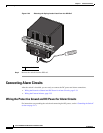
Connecting Alarm Circuits
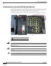
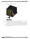
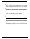
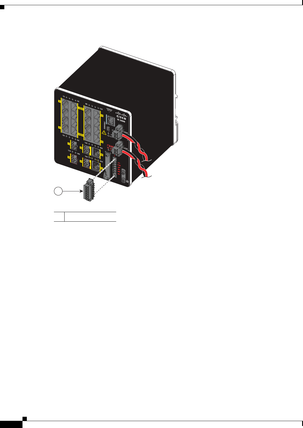
Figure 2-21 Removing the Alarm Connector
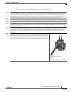
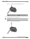
Step 2 Measure two strands of twisted-pair wire (18-to-20 AWG) long enough to connect to the external alarm
device. Choose between setting up an external alarm input or output circuit.
Step 3 Use a wire stripper to remove the casing from both ends of each wire to 0.25 inch (6.3 mm) ± 0.02 inch
(0.5 mm). Do not strip more than 0.27 inch (6.8 mm) of insulation from the wires. Stripping more than
the recommended amount of wire can leave exposed wire from the alarm connector after installation.
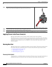
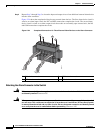
Step 4 Insert the exposed wires for the external alarm device into the connections based on an alarm input or
output circuit setup (see Table 2-3). For example, to wire an alarm input circuit, complete the IN1 and
REF connections (See Figure 2-22).
1 Alarm connector
16TC
±12/24/48
0.5-3.0A
332048
1