


2-35
Cisco IE 2000 Switch Hardware Installation Guide
OL-25818-04
Chapter 2 Switch Installation
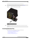
Connecting Alarm Circuits
Wiring the External Alarms
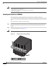
The switch has two alarm input and one alarm output relay circuits for external alarms. The alarm input
circuits are designed to sense if the alarm input is open or closed relative to the alarm input reference
pin. Each alarm input can be configured as an open or closed contact. The alarm output relay circuit has
a normally open and a normally closed contact.
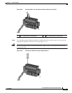
Alarm signals are connected to the switch through the six-pin alarm connector. Three connections are
dedicated to the two alarm input circuits: alarm input 1, alarm input 2, and a reference ground. An alarm
input and the reference ground wiring connection are required to complete a single alarm input circuit.
The three remaining connections are for the alarm output circuit: a normally open output, a normally
closed output, and a common signal. An alarm output and the common wiring connection are required
to complete a single alarm output circuit.
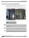
The labels for the alarm connector are on the switch panel and are displayed in Table 2-3.
Warning
Explosion Hazard—Do not connect or disconnect wiring while the field-side power is on; an
electrical arc can occur. This could cause an explosion in hazardous location installations. Be sure
that power is removed or that the area is nonhazardous before proceeding.
Statement 1081
Caution The input voltage source of the alarm output relay circuit must be an isolated source and limited to less
than or equal to 24 VDC, 1.0 A or 48 VDC, 0.5 A.
Note Wire connections to the power and alarm connectors must be UL- and CSA-rated, style 1007 or 1569
twisted-pair copper appliance wiring material (AWM) wire (such as Belden part number 9318).
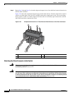
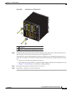
To wire the switch to an external alarm device, follow these steps:
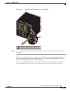
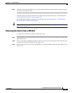
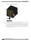
Step 1 Remove the captive screws that hold the alarm connector on the switch, and remove the connector from
the switch chassis. See Figure 2-21.
Table 2-3 Alarm Connector Labels (Top to Bottom)
Label Connection
NO Alarm Output Normally Open (NO) connection
COM Alarm Output Common connection
NC Alarm Output Normally Closed (NC) connection
IN2 Alarm Input 2
REF Alarm Input Reference Ground connection
IN1 Alarm Input 1