


B-18
Cisco IE 3000 Switch Hardware Installation Guide
OL-13017-01
Appendix B Installation In a Hazardous Environment
Verifying Switch Operation
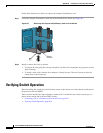
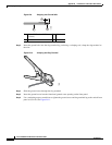
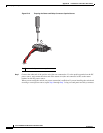
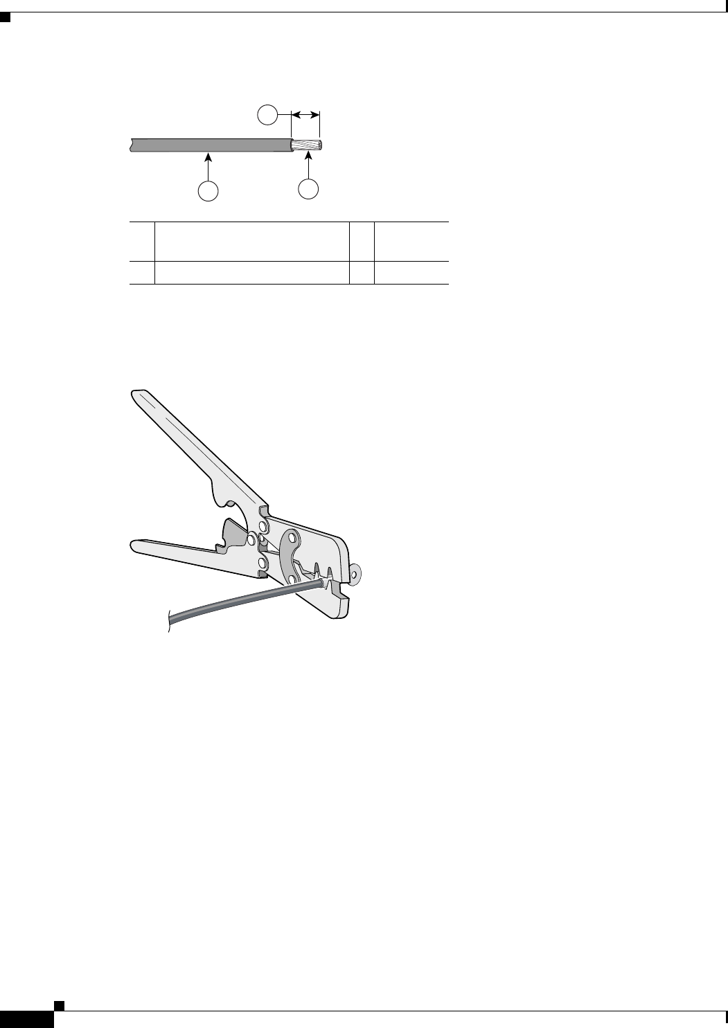
Figure B-9 Stripping the Ground Wire
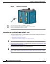
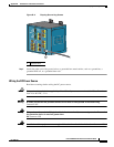
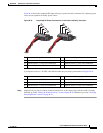
Step 3 Insert the ground wire into the ring terminal lug, and using a crimping tool, crimp the ring terminal to
the wire.
Figure B-10 Crimping the Ring Terminal
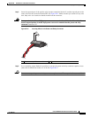
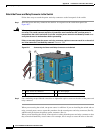
Step 4 Slide the ground screw through the ring terminal.
Step 5 Insert the ground screw into the functional ground screw opening on the front panel.
Step 6 Use a ratcheting torque screwdriver to tighten the ground screw and ring terminal lug to the switch front
panel to 8.5 in-lb. See
Figure B-11.
1 0.5 in. (12.7 mm) ± 0.02 in.
(0.5 mm)
3 Wire lead
2 Insulation
104908
2
1
3
76666