


B-21
Cisco IE 3000 Switch Hardware Installation Guide
OL-13017-01
Appendix B Installation In a Hazardous Environment
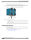
Verifying Switch Operation
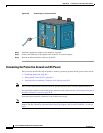
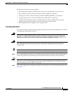
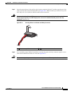
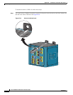
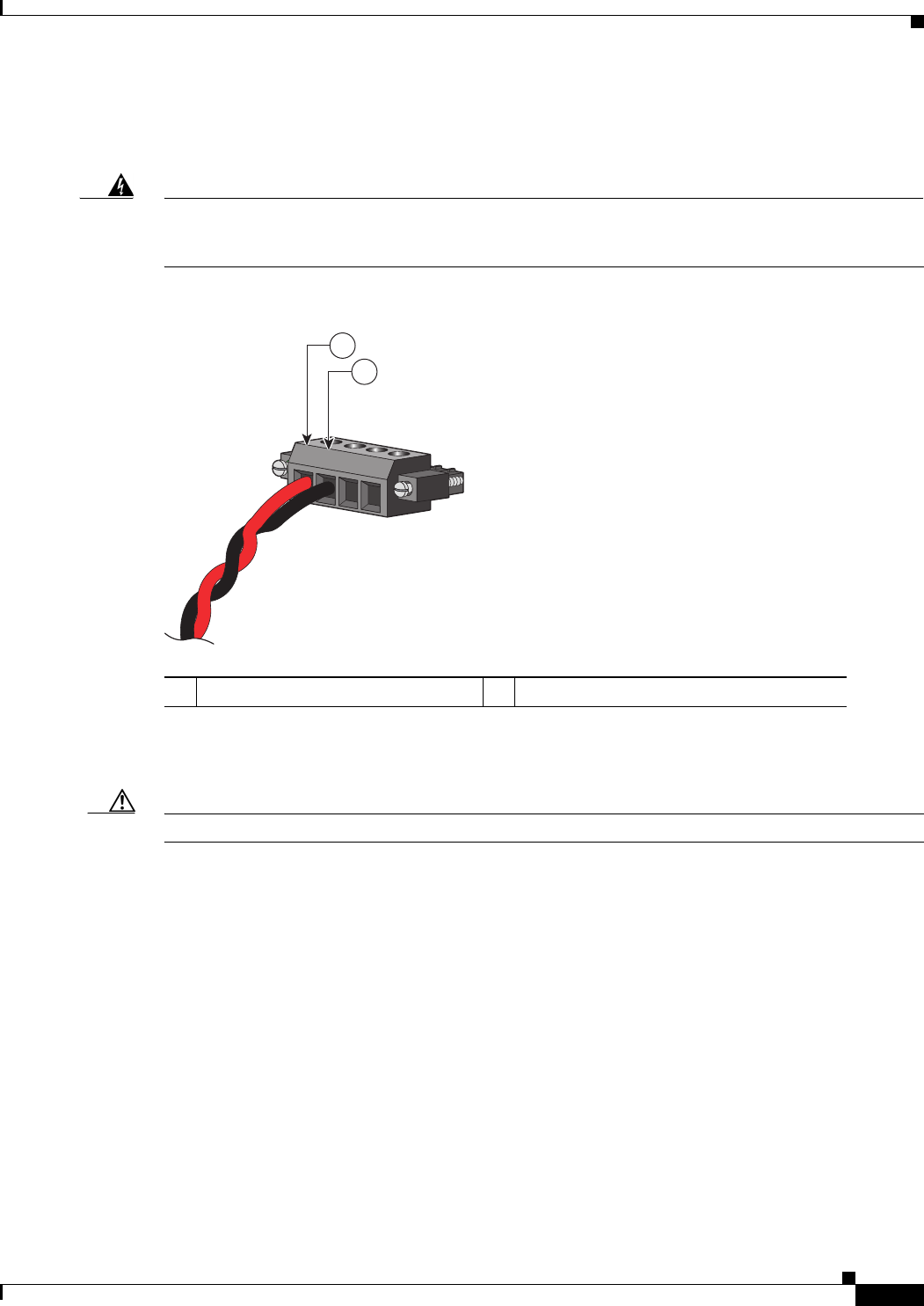
Step 5 Insert the exposed part of the positive wire into the connection labeled V and the exposed part of the
return wire into the connection labeled RT. See
Figure B-14. Make sure that you cannot see any wire
lead. Only wire with insulation should extend from the connector.
Warning
An exposed wire lead from a DC-input power source can conduct harmful levels of electricity. Be sure
that no exposed portion of the DC-input power source wire extends from the power and relay
connector.
Statement 122
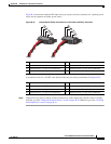
Figure B-14 Inserting Wires in the Power and Relay Connector
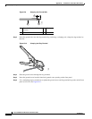
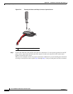
Step 6 Use a ratcheting torque flathead screwdriver to torque the power and relay connector captive screws
(above the installed wire leads) to 2 in-lb. See
Figure B-15.
Caution Do not over-torque the power and relay connector captive screws. The torque should not exceed 2 in-lb.
1 Power source positive connection 2 Power source return connection
202028
RT
A
V
A
1
2