


C-4
Cisco IE 3000 Switch Hardware Installation Guide
OL-13017-01
Appendix C Cable and Connectors
Cable and Adapter Specifications
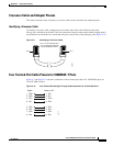
Dual-Purpose Ports
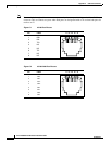
The Ethernet port on a dual-purpose port uses standard RJ-45 connectors. Figure C-2 shows the pinouts.
The SFP module slot on a dual-purpose port uses SFP modules for fiber-optic and copper uplink ports.
See the switch release notes for a list of supported SFP modules.
The auto-MDIX feature is enabled by default. For configuration information for this feature, see the
switch software configuration guide or the switch command reference.
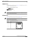
Console Port
The console port uses an 8-pin RJ-45 connector, which is described in Table C-2 and Table C-2. The
supplied RJ-45-to-DB-9 adapter cable is used to connect the console port of the switch to a console PC.
You need to provide a RJ-45-to-DB-25 female DTE adapter if you want to connect the switch console
port to a terminal. You can order a kit (part number ACS-DSBUASYN=) containing that adapter from
Cisco. For console port and adapter pinout information, see
Table C-2 and Table C-3.
Cable and Adapter Specifications
These sections describe the cables and adapters used with Cisco IE 3000 switches.
• SFP Module Cable Specifications, page C-4
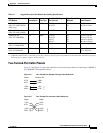
• Two Twisted-Pair Cable Pinouts, page C-5
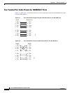
• Four Twisted-Pair Cable Pinouts for 1000BASE-T Ports, page C-6
• Crossover Cable and Adapter Pinouts, page C-7
• Four Twisted-Pair Cable Pinouts for 1000BASE-T Ports, page C-6
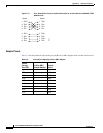
SFP Module Cable Specifications
Table C-1 lists the cable specifications for the rugged fiber-optic SFP module connections. Each port
must match the wave-length specifications on the other end of the cable, and for reliable
communications, the cable must not exceed the required cable length. Copper 1000BASE-T SFP
transceivers use standard four twisted-pair, Category 5 or greater cable at lengths up to 328 feet (100
meters).