


B-39
Cisco IE 3000 Switch Hardware Installation Guide
OL-13017-01
Appendix B Installation In a Hazardous Environment
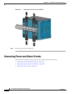
Connecting Power and Alarm Circuits
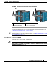
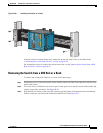
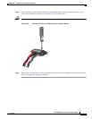
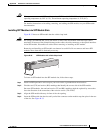
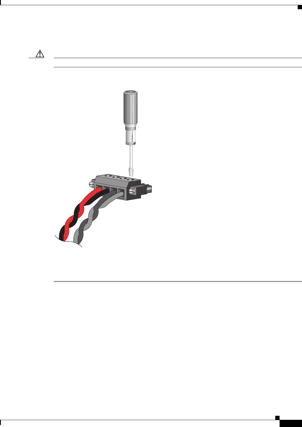
Step 4 Use a ratcheting torque flathead screwdriver to torque the power and relay connector captive screw
(above the installed wire leads) to 2 in-lb. See
Figure B-29 for details.
Caution Do not over-torque the power and relay connector captive screws. The torque should not exceed 2 in-lb.
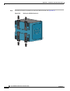
Figure B-29 Torquing the Power and Relay Connector Captive Screws
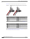
Step 5 Repeat Step 1 through Step 4 to insert the input and output wires of an additional external alarm device
into the second power and relay connector.
202030
RT
A
V
A