


B-40
Cisco IE 3000 Switch Hardware Installation Guide
OL-13017-01
Appendix B Installation In a Hazardous Environment
Connecting Power and Alarm Circuits
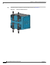
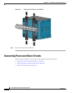
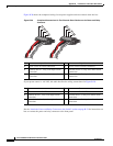
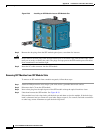
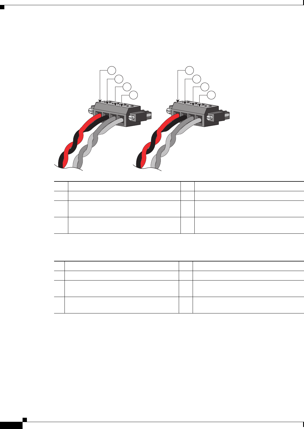
Figure B-30 shows the completed wiring for two power supplies and two external alarm devices.
Figure B-30 Completed Connections for Two External Alarm Devices on the Power and Relay
Connector
If your power source is –48 VDC, this table descibes the wiring connections for Figure B-30.
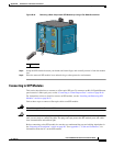
See the “Attach the Power and Relay Connector to the Switch” section on page B-24 for instructions on
how to connect the power and relay connector to the front panel.
1 Power source A positive connection 5 Power source B positive connection
2 Power source A return connection 6 Power source B return connection
3 External device 1, relay wire major alarm
connection
7 External device 2, relay wire minor alarm
connection
4 External device 1, relay wire major alarm
connection
8 External device 2, relay wire minor alarm
connection
201820
RT
A
V
A
RT
A
V
A
1
2
3
4
5
6
7
8
1 Power source A return connection 5 Power source B return connection
2 Power source A –48 VDC connection 6 Power source B –48 VDC connection
3 External device 1, relay wire major alarm
connection
7 External device 2, relay wire minor alarm
connection
4 External device 1, relay wire major alarm
connection
8 External device 2, relay wire minor alarm
connection