


1-10
Cisco IE 3000 Switch Hardware Installation Guide
OL-13017-01
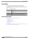
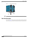
Chapter 1 Overview
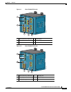
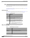
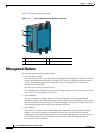
Front-Panel Description
Note The Pwr A and Pwr B LEDs show that power is not present on the switch if the power input drops below
the low valid level. The power status LEDs only show that power is present if the voltage at the switch
input exceeds the valid level. The difference, or hysteresis, ensures that the power status LEDs do not
oscillate at values near 18 V.
For information about the power LED colors during the power-on self-test (POST), see the “Verifying
Switch Operation” section on page 2-11.
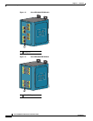
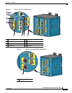
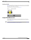
10/100 Port Status LEDs
Each 10/100 port has a port status LED, also called a port LED, as shown in Figure 1-6, Figure 1-7, and
Figure 1-8. Table 1-6 displays LED information about the switch and the individual ports.
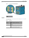
100Base-FX Port Status LEDs
These LEDs display information about the individual ports. See Table 1-7.
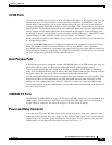
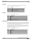
Table 1-6 10/100 Port Status LEDs
Color System Status
Off No link.
Solid green Link present.
Blinking green Activity. Port is sending or receiving data.
Blinking
amber
A link blocked by Spanning Tree Protocol (STP) is
sending or receiving data.
Alternating
green-amber
Link fault. Error frames can affect connectivity, and errors
such as excessive collisions, CRC errors, and alignment and
jabber errors are monitored for a link-fault indication.
Solid amber Port is not forwarding. Port was disabled by management, an
address violation, or STP.
Note After a port is reconfigured, the port LED can remain
amber for up to 30 seconds while STP checks the
switch for possible loops.
Table 1-7 100BASE-FX MM Uplink Port Status LEDs
Color System Status
Off No link.
Solid green Link is present.
Blinking green Activity. Port is sending or receiving data.
Blinking amber A link blocked by Spanning Tree Protocol (STP) is sending or receiving
data.
Alternating green-amber Link is faulty.
Solid amber Link is disabled.