


3-2
Cisco IE 3000 Switch Hardware Installation Guide
OL-13017-01
Chapter 3 Troubleshooting
Diagnosing Problems
Warning
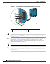
If you connect or disconnect the console cable with power applied to the switch or any device on the
network, an electrical arc can occur. This could cause an explosion in hazardous location
installations. Be sure that power is removed or the area is nonhazardous before proceeding.
To verify switch operation, perform POST on the switch in a nonhazardous location before
installation.
Statement 1065
Verify Switch LEDs
If you have physical access to the switch, look at the port LEDs for information about the switch. See
the
“LEDs” section on page 1-6 for a description of the LED colors and their meanings.
Verify Switch Connections
Review this section when troubleshooting switch connection problems.
Bad or Damaged Cable
Always make sure that the cable does not have marginal damage or failure. A cable might be connect at
the physical layer, but it could corrupt packets as a result of subtle damage to the wiring or connectors.
If the port has many packet errors or the port constantly flaps (loses and regains link):
• Exchange the copper or fiber-optic cable with a known, good cable.
• Look for broken, bent, or missing pins on cable connectors.
• Rule out any bad patch panel connections or media convertors between the source and destination.
If possible, bypass the patch panel, or eliminate faulty media convertors (fiber-optic-to-copper).
• Try the cable in another port or interface, if possible, to see if the problem follows the cable.
Ethernet and Fiber Cables
Make sure that you have the correct cable type for the connection:
• Ethernet, use Category 3 copper cable for 10 Mb/s UTP connections
Use either Category 5, Category 5e, or Category 6 UTP for 10/100 or 10/100/1000 Mb/s
connections.
• Fiber-optic connectors
Verify that you have the correct cable for the distance and the port type. Make sure that the
connected device ports both match and use the same type encoding, optical frequency, and fiber
type. For more information about cabling, see the
“Cable and Adapter Specifications” section on
page C-4.
• Copper connections
Determine if a crossover cable was used when a straight-through was required or the reverse. Enable
auto-MDIX on the switch, or replace the cable. See the
“Cable and Adapter Specifications” section
on page C-4 for recommended Ethernet cables.