


Installing a LightStream 2020 Switch 2-13
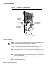
Applying System Power
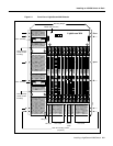
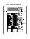
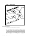
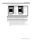
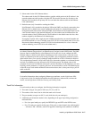
Figure 2-5 LightStream 2020 AC and DC Power Trays
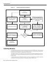
Note When the LS2020 switch is powered up, the blowers start running and the test and control
system (TCS) appliespower tothe cards and initiatesthe power-on self test(POST) sequence. LEDs
on the power tray(s)and the individual cardsindicate operational status, asreflected in the flow chart
in Figure 2-6. The power-up sequence, including the POST, takes a minute or less.
Step 3 If the green ready (RDY) LED on each card lights up (indicating operational status),
proceed to the next section “Installing Modems.” If a yellow fault (FLT) LED stays lit on
any card, indicating the existence of a problem, do either of the following:
• Refer to the LightStream 2020 Hardware Reference & Troubleshooting Guide to
determine why the FLT LED indication occurred and how to correct it.
• Temporarilyremovethe faulty cardfrom the LS2020chassis and bring upthe rest ofthe
system.
Power inlet
Power switch
H3671
Terminal
block
Power
switch
Terminal
block
Power inlet
Power switch
Power
switch
Chassis with
DC power trays
Chassis with
AC power trays