


5
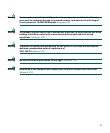
Follow these steps to set up your switch before you run the initial configuration. Your switch might
look different from the illustrations in these steps, but the instructions apply to all the Cisco ME
switches. Instructions for connecting the power source depend on whether the switch is powered
through AC or DC power.
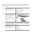
Step 1
Obtain and make note of this
information from your network
administrator before you start the
setup program:
• Switch IP address
• Subnet mask (IP netmask)
• Default gateway (router)
• Enable secret password
• Enable password
• Telnet password
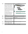
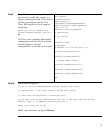
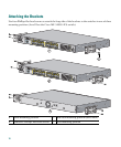
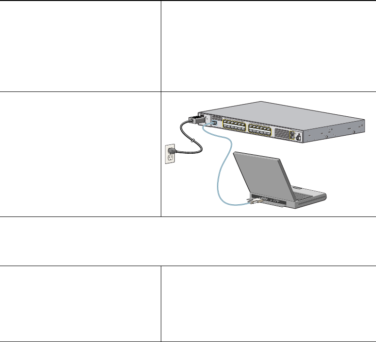
Step 2
Use an RJ-45-to-DB-9 adapter cable
(console cable) to insert the RJ-45
connector into the console port on
the front of the switch.
You must supply the console cable if
you did not order one with your
switch.
This illustration shows the Cisco ME
AC switch.
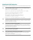
Step 3
Before you power on the switch, start the terminal emulation session so that you see the
output display from the power-on self-test (POST). The terminal-emulation software—a
PC application such as Hyperterminal or ProcommPlus—makes communication between
the switch and your PC or terminal possible.
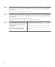
Step 4
Configure the baud rate and
character format of the PC or
terminal to match these console port
default characteristics:
• 9600 baud
• 8 data bits
• 1 stop bit
• No parity
• None (flow control)
C
is
c
o
M
E
3
4
0
0
S
E
R
IE
S
C
O
N
S
O
L
E
1
2
3
4
5
6
7
8
9
1
0
1
1
1
2
1
X
2
X
1
1
X
1
2
X
1
4
1
5
1
6
1
7
1
8
1
9
2
0
2
1
2
2
2
3
2
4
1
3
1
3
X
1
4
X
2
3
X
2
4
X
1
2
S
Y
S
T
E
M
R
AT
IN
G
10
0-2
40V
~
1A
-0.5A
, 5
0-6
0 H
Z
132847