


6
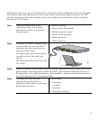
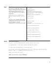
Step 5
Connect the switch to a power
source. For information about the
power consumption for each Cisco
ME switch, see the “Installation
Guidelines” section in Chapter 2 of
the hardware installation guide.
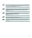
This illustration shows the Cisco ME
DC switch. Connect one end of the
supplied DC power cord to the power
connector on the switch front panel.
Connect the other end of the power
cable to a DC outlet.
For detailed instructions about
connecting to a DC power source, see
the “Connecting to DC Power”
appendix in the switch hardware
installation guide available on
Cisco.com.
Note Use only one of the ground connections,
either the one on the front panel or the
one on the rear panel.
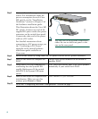
Step 6
Power on the switch by using either the AC power cord or the DC power connector.
Step 7
Wait for the switch to complete the
POST.
It might take several minutes for the switch to
complete POST.
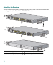
Step 8
Verify that POST has completed by
confirming that the System LED
rapidly blinks green. If the switch
fails POST, the System LED turns
amber.
POST errors are usually fatal. Call Cisco Systems
immediately if your switch fails POST.
Step 9
Wait for the switch to complete flash
initialization. When you see this
prompt, press Return or Enter.
Press RETURN to get started!
Step 10
Go to the “Completing the Initial Configuration” section on page 7.
Cisco ME 3400
S
ER
IE
S
INP
U
T -36
–
-
72
V
C
UR
RE
NT
2
–
1A
A
B
+
+
C
O
N
S
O
L
E
1
2
3
4
5
6
7
8
9
1
0
1
1
1
2
1
X
2X
11
X
1
2X
1
4
15
1
6
17
18
19
20
2
1
2
2
23
24
13
1
3
X
1
4
X
2
3
X
2
4
X
SY
ST
EM
1
2
132848