


10
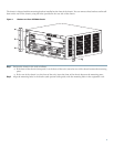
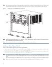
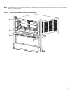
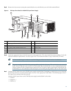
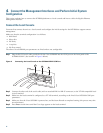
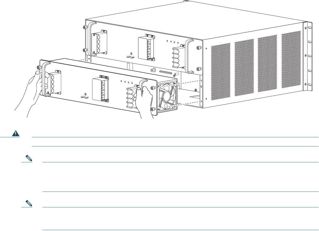
Step 3 Verify that power is off to the DC circuit connected to the power supply you are installing. Grasp both power supply
handles, as shown in Figure 5 on page 10. Slide the power supply into the power supply bay. Make sure that the power
supply is fully seated in the bay.
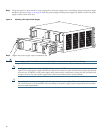
Figure 5 Handling a DC-Input Power Supply
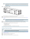
Step 4 Tighten the power supply captive installation screws.
Warning
Power supply captive installation screws must be tight to ensure protective grounding continuity.
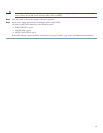
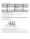
Note As the power requirement of the SCE8000 will not exceed 1350W, it is not necessary to connect two pairs of
input wires to each power supply. Should it be desired to connect two pairs of input wires, both pairs of input
wires for one 2700W DC-input power supply must come from the same battery system (A feed); and both pairs
of input wires for the other power supply must come from another battery system (B feed).
Note For multiple DC input power supply, each DC input must be protected by dedicated circuit breaker or fuse.
The circuit breaker or fuse should be sized according to the power supply input rating and local or national
electrical code requirements.
126567
PWR-2700-DC/4
A
L
L
F
A
S
T
E
N
E
R
S
M
U
S
T
B
E
F
U
L
LY
E
N
G
A
G
E
D
P
R
IO
R
T
O
O
P
E
R
A
T
IN
G
T
H
E
P
O
W
E
R
S
U
P
P
L
Y
INP
U
T1
O
K
48V-60V
=40A
IN
PU
T
2
O
K
48V-60V
=40A
F
AN
O
K
O
U
TP
U
T
FAI L
+VE-1
-VE-1
+VE-2
-VE-2
A
L
L
F
A
S
T
E
N
E
R
S
M
U
S
T
B
E
F
U
L
L
Y
E
N
G
A
G
E
D
P
R
IO
R
T
O
O
P
E
R
A
T
IN
G
T
H
E
P
O
W
E
R
S
U
P
P
L
Y
IN
PU
T1
O
K
48V-60V
=
40A
IN
PUT
2
O
K
48V-60V
=40
A
FA
N
O
K
O
UTP
UT
FA
I
L
PWR-2700-DC/4
+VE-1
-VE-1
+VE-2
-VE-2
+VE-1
-VE-1
+VE-2
-VE-2
+VE-1
-VE-1
+VE-2
-VE-2