


12
Note When you tighten the terminal nuts, make sure they are snug. Do not over tighten them. Recommended torque
strength is 20 inch-pounds. Over tightening the terminal nuts can break the terminal block (Maximum torque:
36 inch-pounds).
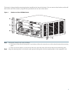
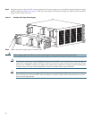
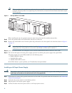
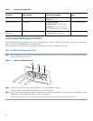
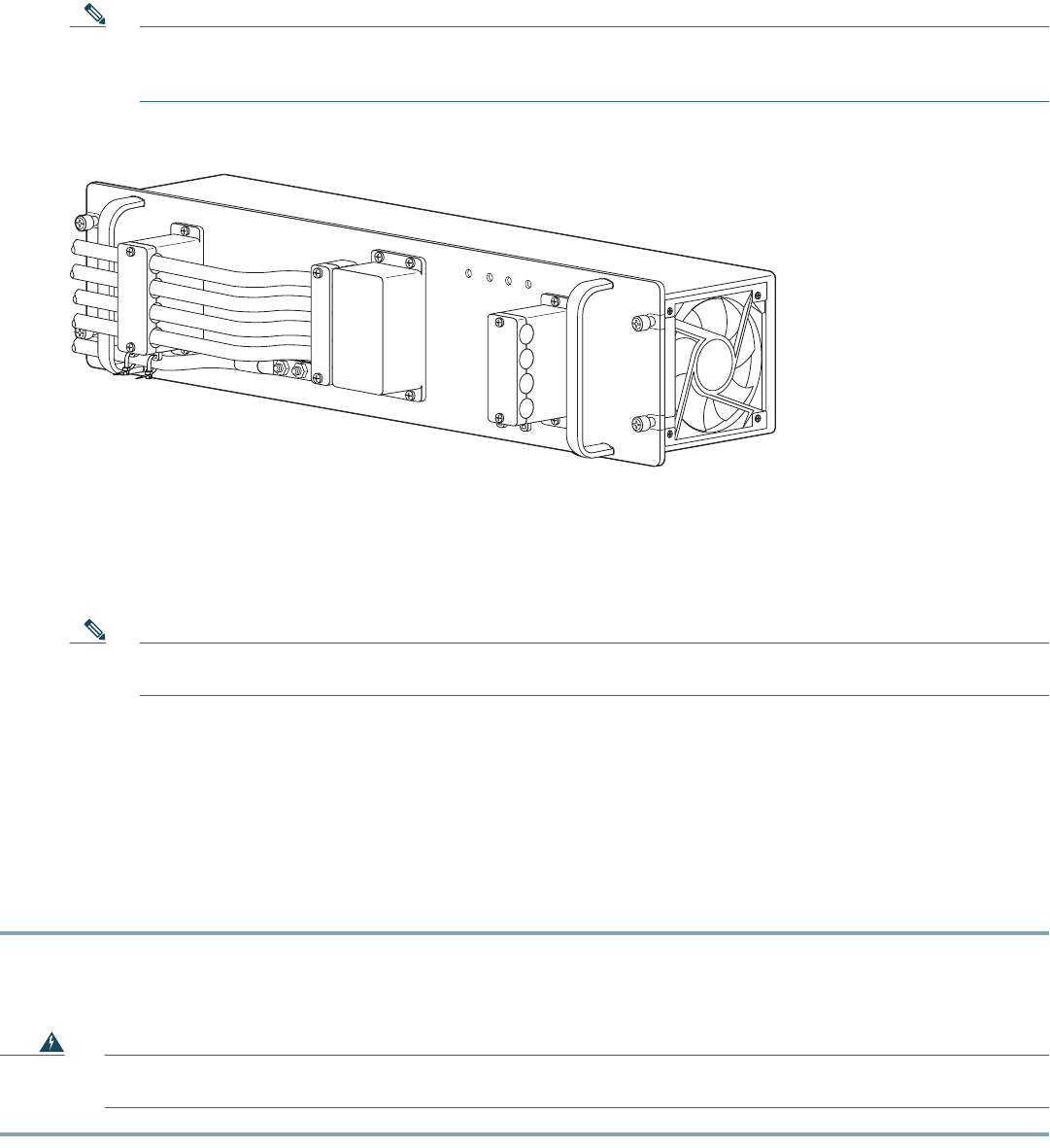
Figure 7 DC-Input Wires on Left Side
When installing the unit, the ground connection must always be made first and disconnected last.
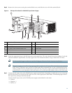
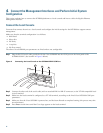
Step 8 Secure the ground cable to the cable holder with the two cable-ties.
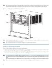
Step 9 Retrieve the cable holder covers from the plastic bag and attach to the front panel at the locations shown in Figure 6
on page 11.
Note If the cable holder illustrated as number 5 and 8 in Figure 6 on page 11 does not hold the DC input cables
snugly, please use a long cable tie to secure the cable holders as illustrated in number 9.
Step 10 Secure the terminal block cover using four screws and the terminal block barriers with two screws each.
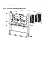
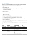
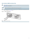
Step 11 Turn on the DC inputs and verify power supply operation by checking the power supply front panel LEDs.
The power supply rear panel LEDs should be in the following states:
• INPUT OK LED is green
• FAN OK LED is green
• OUTPUT FAIL LED is not lit
If the LEDs indicate a power problem, see 7Troubleshoot Startup Problems.
Installing an AC-Input Power Supply
Warning
This product requires short-circuit (over current) protection, to be provided as part of the building installation.
Install only in accordance with national and local wiring regulations.
Step 1 Ensure that the system (earth) ground connection has been made. For ground connection instructions, see Connect the
Chassis Ground, page 8.
Step 2 Verify that the power switch is in the Off (0) position.
Step 3 Plug the power cord into the power supply.
Step 4 Connect the other end of the power cord to an AC-input power source.
132220
IN
P
U
T1
O
K
48
V-60V
=40A
IN
PU
T
2
O
K
4
8V-60V
=40A
FA
N
O
K
O
U
TP
U
T
FAIL
ALL FASTEN
ERS M
UST BE FULLY ENGAG
ED
PRIOR
TO OPERATING THE POW
ER SUPPLY
PWR-2700-DC/4