


13
Cisco uBR10-LCP2-MC28C Cable Interface Line Card for the Cisco uBR10012 Router
OL-4653-01
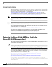
Installing a Cisco uBR10-LCP2-MC28C Cable Interface Line Card
Step 1 Attach an antistatic wrist strap to your wrist and to a bare metal, unpainted surface on the chassis or
frame.
Step 2 Face the back of the Cisco uBR10012 chassis. Clear enough interface and power cables to allow
sufficient space to work.
Step 3 If installing a new cable interface line card in a blank slot, remove the blank slot cover and discard it.
Otherwise, disconnect all coaxial cables from the cable interface line card being replaced or removed.
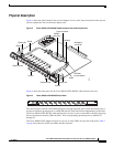
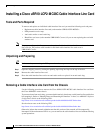
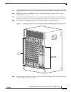
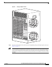
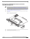
Step 4 Unscrew the top and bottom captive screws on the cable interface line card (Figure 5).
Figure 5 Locating the Captive Screws on the Cisco uBR10-LCP2-MC28C Cable Interface Line Card
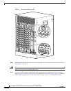
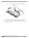
Step 5
Simultaneously pivot both ejector levers away from each other to disengage the cable interface line card
from the backplane (Figure 6 on page 14).
56301
US2
US0
US1
US2
US3
DS0
uBR - MC28C
E
N
A
B
L
E
D
US1
DS1
US0
US3
US2
US0
US1
US2
US3
DS0
uBR - MC28C
E
N
A
B
L
E
D
US1
DS1
US0
US3
US2
US0
US1
US2
US3
DS0
uBR - MC28C
E
N
A
B
L
E
D
US1
DS1
US0
US3
US2
US0
US1
US2
US3
DS0
uBR - MC28C
E
N
A
B
L
E
D
US1
DS1
US0
US3
US2
US0
US1
US2
US3
DS0
uBR - MC28C
E
N
A
B
L
E
D
US1
DS1
US0
US3
US2
US0
US1
US2
US3
DS0
uBR - MC28C
E
N
A
B
L
E
D
US1
DS1
US0
US3
US2
US0
US1
US2
US3
DS0
uBR - MC28C
E
N
A
B
LE
D
US1
DS1
US0
US3
US2
US0
US1
US2
US3
DS0
uBR - MC28C
E
N
A
B
L
E
D
US1
DS1
US0
US3
CISCO
10000
C
A
R
R
IE
R
A
L
A
R
M
L
O
O
P
F
A
IL
CH OC-12-DSO SM-IR
CISCO
10000
C
A
R
R
I
E
R
A
L
A
R
M
L
O
O
P
F
A
IL
CH OC-12-DSO SM-IR
CISCO
10000
C
A
R
R
IE
R
A
L
A
R
M
L
O
O
P
F
A
IL
CH OC-12-DSO SM-IR
CISC
100
C
A
R
R
IE
R
A
L
A
R
M
L
F
A
IL
Captive
screws
Captive
screws