


5
Cisco uBR10-LCP2-MC28C Cable Interface Line Card for the Cisco uBR10012 Router
OL-4653-01
Cisco uBR10-LCP2-MC28C Overview
Physical Description
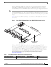
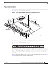
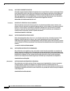
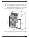
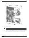
Figure 3 shows the cable interface line card and adapter card as a unit. Note the location of the ejectors
used to separate the line card from the adapter card.
Figure 3 Cisco uBR10-LCP2-MC28C Cable Interface Line Card Components
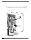
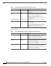
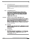
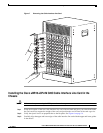
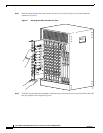
Figure 4 shows the front panel for the Cisco uBR10-LCP2-MC28C cable interface line card.
Figure 4 Cisco uBR10-LCP2-MC28C Front Panel
The cable interface card has two downstream ports and eight upstream ports. Each downstream port is
associated with four upstream ports in a DOCSIS domain. Each domain runs independently of the other.
The Cisco uBR10-LCP2-MC28C cable interface line card uses a color-coded label to identify and group
the two downstream domains (DS0 and DS1). Their corresponding upstream ports are labeled U0
through U3.
The Cisco uBR10-LCP2 adapter card has its own set of status LEDs on top of the front panel. Table 2
on page 6 describes the LCP2 card LEDs and their function.
58720
Captive screw
Captive screw
Handle
Ejector
Ejector
Guide
Guide
Ejector tab
Ejector tab
LCP2 connector
Backplane
connector
MC28C
connector
L-Bracket
L-Bracket
nut and washer
uBR-MC28C
US1
US0
US2
US3
US4
US5
US6
US7
DS0
DS1
ENABLED
US2
US0
US1
US2
US3
DS0
uBR - MC28C
ENABLED
US1
DS1
US0
US3
56419