


22
Cisco uBR10-LCP2-MC28C Cable Interface Line Card for the Cisco uBR10012 Router
OL-4653-01
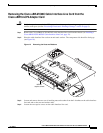
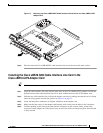
Replacing the Cisco uBR-MC28C Line Card in the Cisco uBR10-LCP2 Adapter Card
Note These brackets help align the adapter card and Cisco uBR-MC28C cable interface line card connectors
and hold the Cisco uBR-MC28C cable interface line card in place.
Step 6 Tighten the captive screws on the Cisco uBR-MC28C cable interface line card to secure it to the
Cisco uBR10-LCP2 adapter card.
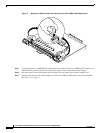
Step 7 Replace the retaining washers and retaining nuts on the L-brackets (see Figure 11 on page 20). Make
sure they are finger-tight and then turn them a half-turn with a wrench to secure them and the
Cisco uBR-MC28C cable interface line card.
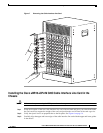
Replacing the Cisco uBR10-LCP2-MC28C Cable Interface Line Card in the
Chassis
Tip Make sure that you are using the ESD-preventive wrist strap.
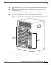
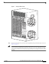
Step 1 Grasp the faceplate of the new cable interface line card with one hand and place your other hand under
the card carrier (to support the weight of the card) and position the card in front of the card cage slot.
Step 2 Carefully align the upper and lower edges of the cable interface line card with the upper and lower guides
in the chassis, and slide the card into the slot until you can feel it begin to seat in the backplane
connectors (Figure 8 on page 16).
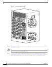
Step 3 Simultaneously pivot both ejector levers toward each other (until they are parallel to the faceplate) to
firmly seat the card in the backplane (Figure 9 on page 17).
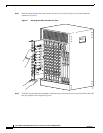
Step 4 Secure the cable interface line card in the chassis by tightening the top and bottom captive screws (see
Figure 5 on page 13).
Caution To ensure that there is adequate space for additional cable interface line cards, always tighten the captive
screws on each newly installed card before you insert any additional cards. These screws prevent
accidental removal and provide proper grounding for electromagnetic interference (EMI) shielding.
Connecting the Cables
When fully inserted, the cable interface line card cycles through its power-on self-test. The Power LED
is on (green) and the Status LED turns yellow. If the card is operating correctly, the Status LED then
turns green. If these LED do not operate as described, refer to the Cisco uBR10012 Universal Broadband
Router Hardware Installation Guide at the following URL:
http://www.cisco.com/univercd/cc/td/doc/product/cable/ubr10k/ubr10012/hig/index.htm