


17
Cisco uBR10-LCP2-MC28C Cable Interface Line Card for the Cisco uBR10012 Router
OL-4653-01
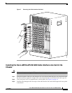
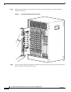
Installing a Cisco uBR10-LCP2-MC28C Cable Interface Line Card
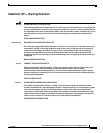
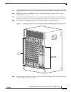
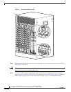
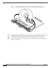
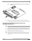
Figure 9 Closing the Ejector Levers
Step 6
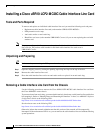
Secure the cable interface line card in the chassis by tightening the top and bottom captive screws (see
Figure 5 on page 13).
Caution To ensure that there is adequate space for additional cable interface line cards, always tighten the captive
screws on each newly installed cable interface line card before you insert any additional cards. These
screws prevent accidental removal and provide proper grounding for electromagnetic interference (EMI)
shielding.
56305
US2
US0
US1
US2
US3
DS0
uBR - MC28C
E
N
A
B
L
E
D
US1
DS1
US0
US3
US2
US0
US1
US2
US3
DS0
uBR - MC28C
E
N
A
B
L
E
D
US1
DS1
US0
US3
US2
US0
US1
US2
US3
DS0
uBR - MC28C
E
N
A
B
L
E
D
US1
DS1
US0
US3
US2
US0
US1
US2
US3
DS0
uBR - MC28C
E
N
A
B
L
E
D
US1
DS1
US0
US3
US2
US0
US1
US2
US3
DS0
uBR - MC28C
E
N
A
B
L
E
D
US1
DS1
US0
US3
US2
US0
US1
US2
US3
DS0
uBR - MC28C
E
N
A
B
L
E
D
US1
DS1
US0
US3
US2
US0
US1
US2
US3
DS0
uBR - MC28C
E
N
A
B
L
E
D
US1
DS1
US0
US3
US2
US0
US1
US2
US3
DS0
uBR - MC28C
E
N
A
B
LE
D
US1
DS1
US0
US3
CISCO
10000
C
A
R
R
IE
R
A
L
A
R
M
L
O
O
P
F
A
IL
CH OC-12-DSO SM-IR
CISCO
10000
C
A
R
R
IE
R
A
L
A
R
M
L
O
O
P
F
A
IL
CH OC-12-DSO SM-IR
CISCO
10000
C
A
R
R
IE
R
A
L
A
R
M
L
O
O
P
F
A
IL
CH OC-12-DSO SM-IR
CISC
100
C
A
R
R
IE
R
A
L
A
R
M
L
F
A
IL
ENABLED
U
S
1
U
S
0
ENABLED
U
S
1
U
S
0
ENABLED
U
S
1
U
S
0
ENABLED
U
S
1
U
S
0
D
S
0
uBR - MC28C
D
S
1
D
S
0
uBR - MC28C
D
S
1
D
S
0
uBR - MC28C
D
S
1
D
S0
uBR - MC28C
D
S
1