


18
Cisco uBR10-LCP2-MC28C Cable Interface Line Card for the Cisco uBR10012 Router
OL-4653-01
Replacing the Cisco uBR-MC28C Line Card in the Cisco uBR10-LCP2 Adapter Card
Connecting the Cables
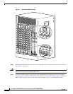
When fully inserted, the cable interface line card cycles through its power-on self-test. The Power LED
turns on (green) and the Status LED turns on (yellow). If the card is operating correctly, the Status LED
turns green. If these LED do not operate as described, refer to
Troubleshooting the Cisco uBR10-LCP2-MC28C Cable Interface Line Card, page 23 and the
Cisco uBR10012 Universal Broadband Router Hardware Installation Guide at the following URL:
http://www.cisco.com/univercd/cc/td/doc/product/cable/ubr10k/ubr10012/index.htm
Note It is not necessary to configure the cable interface line card if you are installing a replacement card in
the identical slot. The system automatically downloads the necessary configuration information from the
PRE1.
Step 1 Connect all downstream and upstream coaxial cables to the cable interface line card.
Step 2 Configure the cable interface line card if necessary.
For information about configuring the cable interface line card, refer to the Cisco uBR10012 Software
Configuration Guide at the following URL:
http://www.cisco.com/univercd/cc/td/doc/product/cable/ubr10k/ubr10012/index.htm
For configuration information, refer to Configuring the Cisco uBR-MC28C Cable Modem Card,
available on the documentation CD-ROM and Cisco.com at the following URL:
http://www.cisco.com/univercd/cc/td/doc/product/cable/cab_r_sw/flmc28.htm.
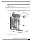
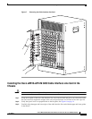
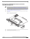
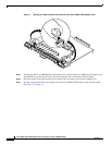
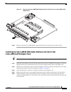
Replacing the Cisco uBR-MC28C Line Card in the
Cisco uBR10-LCP2 Adapter Card
The following section describes how to remove and replace an uBR-MC28C cable interface line card in
a Cisco uBR10-LCP2 adapter card.
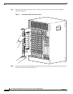
Note Do not attempt to separate or remove the Cisco uBR-MC28C cable interface line card from the
LCP2 adapter card while the combined cards are inserted in the chassis. The cards must be removed as
a unit and then separated on a lab bench or other area that protects against ESD damage.
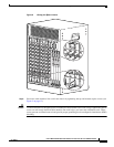
To prevent alarms from activating, you must administratively shut down a cable interface line card before
hot swapping the card. Refer to “Shutting Down and Restarting the Interface” in the Cisco uBR10012
Software Configuration Guide at the following URL:
http://www.cisco.com/univercd/cc/td/doc/product/cable/ubr10k/ubr10012/index.htm
See the release notes at the following URL:
http://www.cisco.com/univercd/cc/td/doc/product/cable/ubr10k/ub10krns/index.htm
Otherwise, inform the network administrator that this portion of the network will be temporarily
interrupted. If the maintenance LED is on, you can remove the cable interface line card without affecting
systems operations.