


13
Cisco uBR7200 Series Universal Broadband Router AC Power Supply Replacement Instructions
78-4848-06
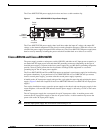
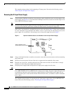
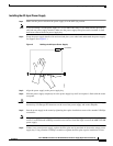
Removing and Replacing an AC-Input Power Supply
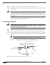
Note Each uBR7246 AC-input power supply has an electrical current rating of 7A. The uBR7225 AC-input
power supply is 4A.
This completes the steps for reconnecting AC-input power to a Cisco uBR7200 series router. Proceed to
the following section, “Powering Up the Router.”
Powering Up the Router
Step 1 Check for the following:
• Each port adapter is inserted in its slot, and the port adapter retention clip is in the locked
position.
Note The Cisco uBR7225VXR router does not support port adapters or the I/O controller. The
Cisco uBR7225VXR power supply device does not have a cable retention clip..
• Each cable modem card is inserted in its slot, and its respective captive installation screws are
tightened.
• The network processing engine and the I/O controller are inserted in their respective slots, and
their captive installation screws are tightened.
• All network interface cables are connected to the port adapters.
• A Flash memory card is installed in its PCMCIA slot (if present).
• Each AC-input power cable is connected and secured with the cable-retention clip.
• The console terminal is turned on.
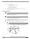
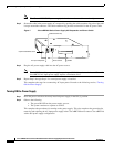
Step 2 At the rear of the router, place the power switch on the power supply in the ON (|) position. Repeat this
step if a second power supply is installed in the router. The green OK LED on the power supply goes on.
Step 3 Listen for the fans; you should immediately hear them operating.
Step 4 During the boot process, observe the system LEDs. The LEDs on most of the port adapters and cable
modem cards go on and off randomly. Some might go on, go out, and go on again for a short time. On
the I/O controller, the IO Power OK LED goes on immediately.
Step 5 Observe the initialization process. When the system boot is complete (after a few seconds), the network
processing engine begins to initialize the port adapters and the I/O controller. During this initialization,
the LEDs on each port adapter behave differently (most flash on and off). The enabled LED on each port
adapter goes on when initialization is completed, and the console screen displays a script and system
banner similar to the following:
Cisco Internetwork Operating System Software
IOS (tm) uBR7200 Software (uBR7200-I-M), Version 11.3(2)XA1 [kpfjrgiu 100]
Copyright (c) 1986-1998 by cisco Systems, Inc.
Compiled Sun 09-Mar-98 04:10 by smith
This completes the procedures for powering up the router. This also completes the procedure for
replacing the AC-input power supply in a single Cisco uBR7200 series power supply configuration.
If you have questions or need assistance, see the “Obtaining Documentation and Submitting a Service
Request” section on page 17. Otherwise, if your Cisco uBR7246VXR or Cisco uBR7246 has a dual
power supply configuration, proceed to the following section, “Dual Power Supply Configuration in the
Cisco uBR7200 Series Routers.”